Subaru Legacy III (2000-2003 year). Service manual — part 612
MT-16
MANUAL TRANSMISSION AND DIFFERENTIAL
GENERAL DESCRIPTION
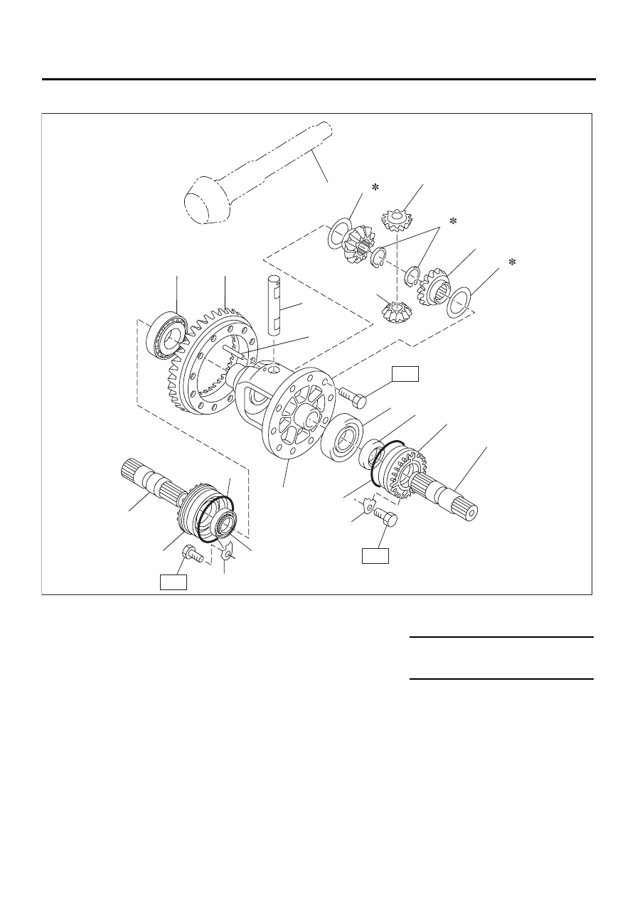
7. FRONT DIFFERENTIAL
(1) Drive pinion shaft
(8) Snap ring (Outer)
(15) Retainer lock plate
(2) Hypoid driven gear
(9) Roller bearing
(3) Pinion shaft
(10) Differential case
Tightening torque: N·m (kgf-m, ft-lb)
(4) Straight pin
(11) Oil seal
T1: 25 (2.5, 18.1)
(5) Washer
(12) Differential side retainer
T2: 62 (6.3, 45.6)
(6) Differential bevel gear
(13) O-ring
(7) Differential bevel pinion
(14) Axle drive shaft
MT-00352
( 1 )
( 2 )
( 3 )
( 4 )
( 5 )
( 5 )
( 6 )
( 7 )
( 7 )
( 8 )
( 9 )
( 9 )
(10)
(11)
(12)
(13)
(14)
(15)
(11)
(12)
(13)
(14)
(15)
T1
T2
T1
MT-17
MANUAL TRANSMISSION AND DIFFERENTIAL
GENERAL DESCRIPTION
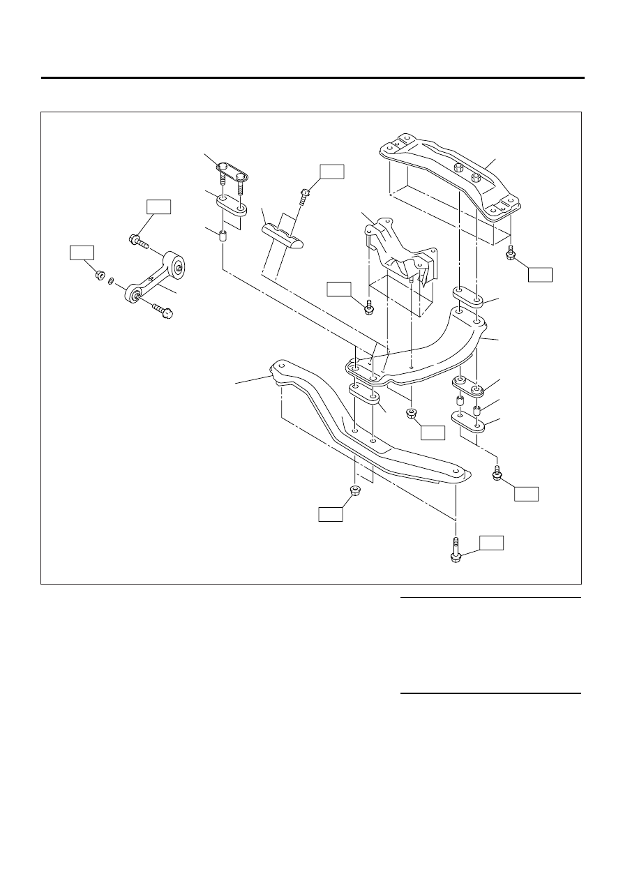
8. TRANSMISSION MOUNTING
(1)
Pitching stopper
(7)
Rear crossmember
Tightening torque: N·m (kgf-m, ft-lb)
(2)
Spacer
(8)
Cushion D
T1: 7.5 (0.76, 5.5)
(3)
Cushion C
(9)
Center crossmember
T2: 35 (3.6, 26)
(4)
Front plate
(10)
Rear plate
T3: 50 (5.1, 37)
(5)
Dynamic damper (Except Austra-
lia TURBO MT model)
(11)
Front crossmember (OUTBACK
model)
T4: 58 (5.9, 43)
T5: 70 (7.1, 51)
(6)
Rear cushion rubber
T6: 140 (14.3, 103)
(1)
T4
T1
T5
T5
T5
T2
T6
T2
T3
(2)
(4)
(6)
(8)
(9)
(8)
(3)
(2)
(10)
(7)
(5)
(3)
(11)
MT-00010
MT-18
MANUAL TRANSMISSION AND DIFFERENTIAL
GENERAL DESCRIPTION
C: CAUTION
• Wear working clothing, including a cap, protec-
tive goggles, and protective shoes during opera-
tion.
• Remove contamination including dirt and corro-
sion before removal, installation, and disassembly.
• Keep the disassembled parts in order and pro-
tect them from dust or dirt.
• Before removal, installation or disassembly, be
sure to clarify the failure. Avoid unnecessary re-
moval, installation, disassembly and replacement.
• When disassembling the case and other light al-
loy parts, use a plastic hammer to force it apart. Do
not pry it apart with a screwdriver or other tool.
• Be careful not to burn your hands, because each
part on the vehicle is hot after running.
• Use SUBARU genuine gear oil, grease etc. or
the equivalent. Do not mix gear oil, grease etc. with
that of another grade or from other manufacturers.
• Be sure to tighten fasteners including bolts and
nuts to the specified torque.
• Place shop jacks or safety stands at the specified
points.
• Apply gear oil onto sliding or revolution surfaces
before installation.
• Replace deformed or otherwise damaged snap
rings with new ones.
• Before installing O-rings or oil seals, apply suffi-
cient amount of gear oil to avoid damage and defor-
mation.
• Be careful not to incorrectly install or fail to install
O-rings, snap rings and other such parts.
• Before securing a part on a vise, place cushion-
ing material such as wood blocks, aluminum plate,
or shop cloth between the part and the vise.
• Avoid damaging the mating surface of the case.
• Before applying sealant, completely remove the
old seal.
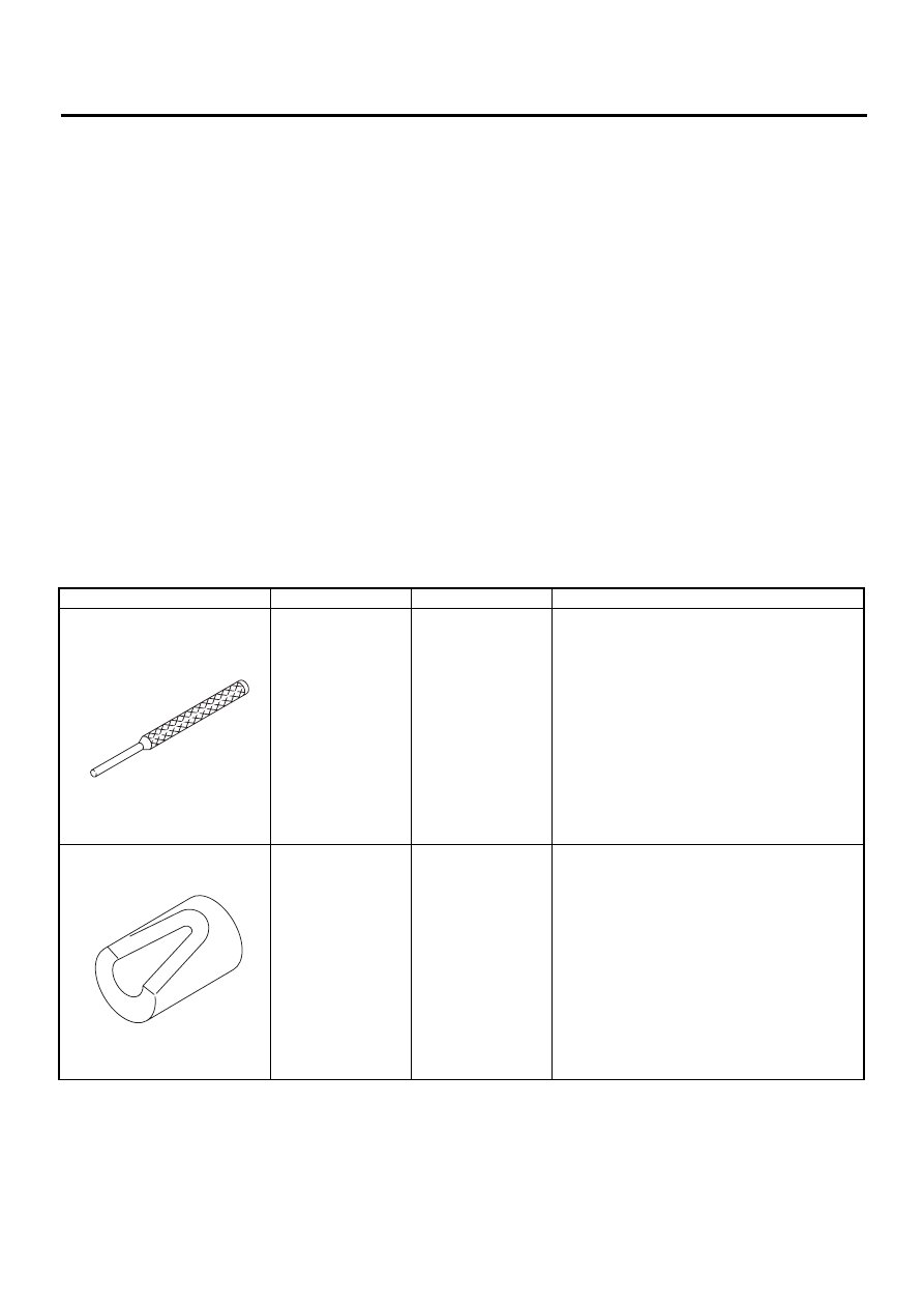
D: PREPARATION TOOL
1. SPECIAL TOOLS
ILLUSTRATION
TOOL NUMBER
DESCRIPTION
REMARKS
398791700
REMOVER II
Used for removing and installing spring pin (6
mm).
399411700
ACCENT BALL
INSTALLER
Used for installing reverse shifter rail arm.
ST-398791700
ST-399411700
MT-19
MANUAL TRANSMISSION AND DIFFERENTIAL
GENERAL DESCRIPTION
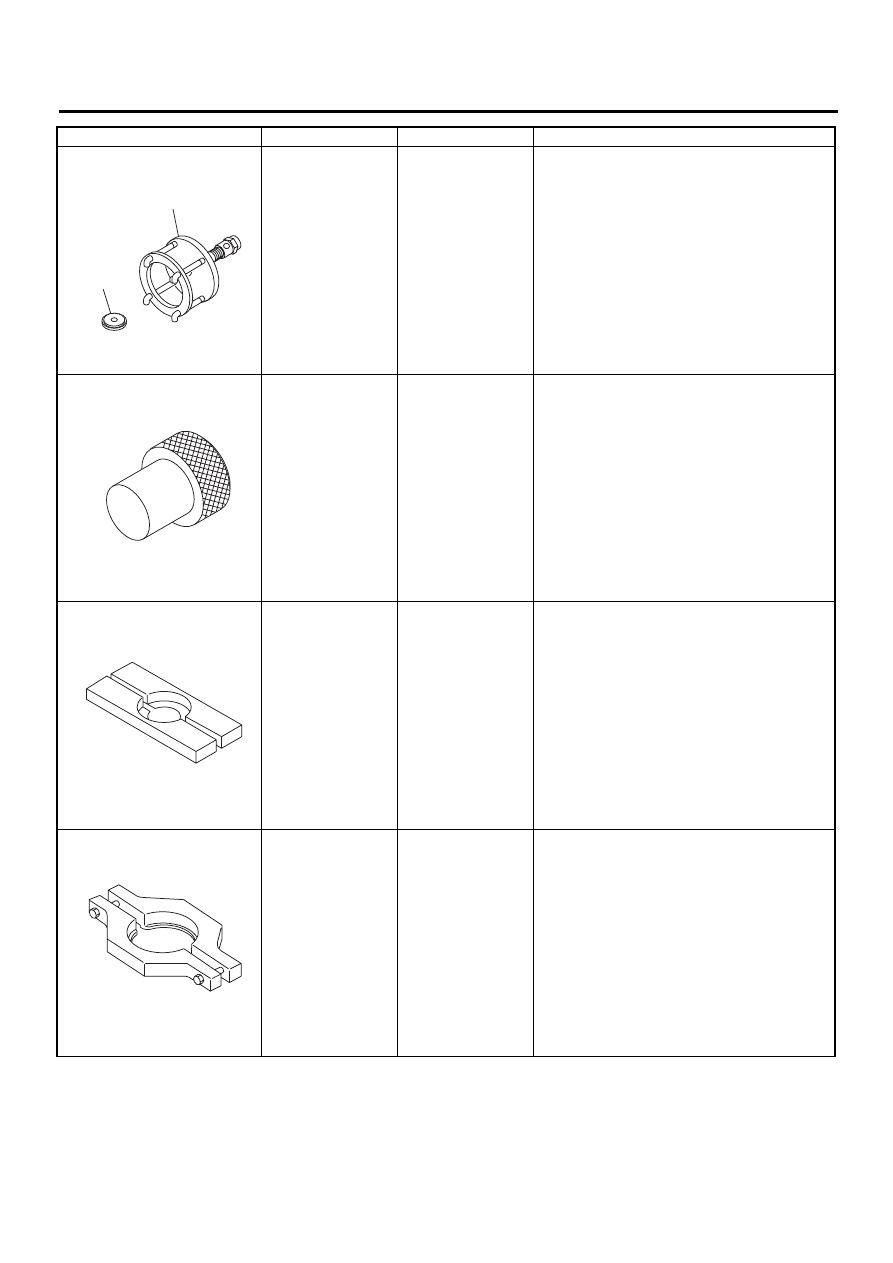
899524100
PULLER SET
Used for removing and installing roller bearing
(Differential).
(1) PULLER
(2) CAP
399780104
WEIGHT
Used for measuring preload on roller bearing.
498077000
5TH DRIVEN GEAR
REMOVER
Used for removing roller bearing of drive pinion
shaft.
498077300
CENTER DIFFER-
ENTIAL BEARING
REMOVER
Used for removing the center differential cover
ball bearing.
ILLUSTRATION
TOOL NUMBER
DESCRIPTION
REMARKS
ST-899524100
( 1 )
( 2 )
ST-399780104
ST-498077000
ST-498077300
Нет комментариевНе стесняйтесь поделиться с нами вашим ценным мнением.
Текст