Subaru Legacy III (2000-2003 year). Service manual — part 412
ME(H4DOSTC)-12
MECHANICAL
GENERAL DESCRIPTION
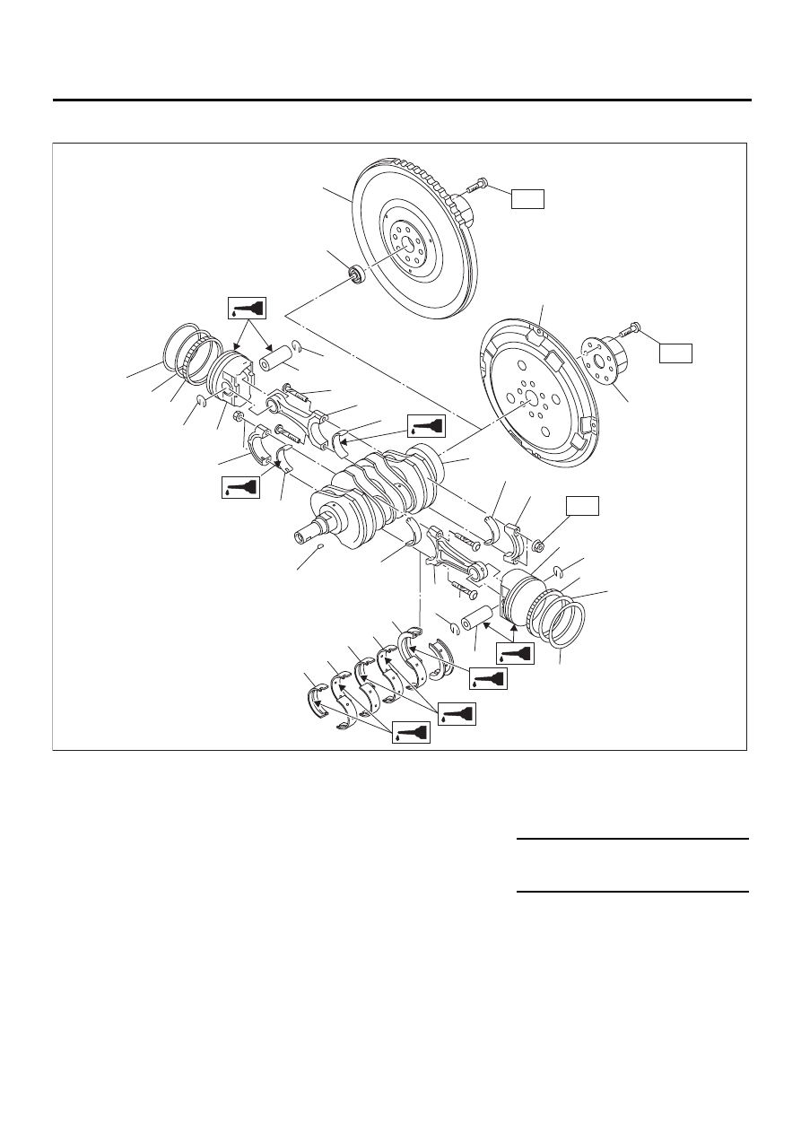
5. CRANKSHAFT AND PISTON
(1) Flywheel (MT vehicles only)
(9) Piston pin
(17) Crankshaft bearing #1, #3
(2) Ball bearing (MT vehicles only)
(10) Circlip
(18) Crankshaft bearing #2, #4
(3) Reinforcement (AT vehicles only)
(11) Connecting rod bolt
(19) Crankshaft bearing #5
(4) Drive plate (AT vehicles only)
(12) Connecting rod
(5) Top ring
(13) Connecting rod bearing
Tightening torque: N·m (kgf-m, ft-lb)
(6) Second ring
(14) Connecting rod cap
T1: 45 (4.6, 33.3)
(7) Oil ring
(15) Crankshaft
T2: 72 (7.3, 52.8)
(8) Piston
(16) Woodruff key
ME-00005
( 9 )
(10)
(10) (11)
( 7 )
( 7 )
( 5 )
( 9 )
(11)
(12)
(12)
( 3 )
( 4 )
(13)
(13)
(13)
(13)
(14)
(14)
(15)
(16)
(10)
(10)
( 6 )
( 6 )
( 5 )
( 8 )
( 2 )
( 1 )
(19)
(17)
(18)
(18)
(17)
T1
( 8 )
T2
T2
ME(H4DOSTC)-13
MECHANICAL
GENERAL DESCRIPTION
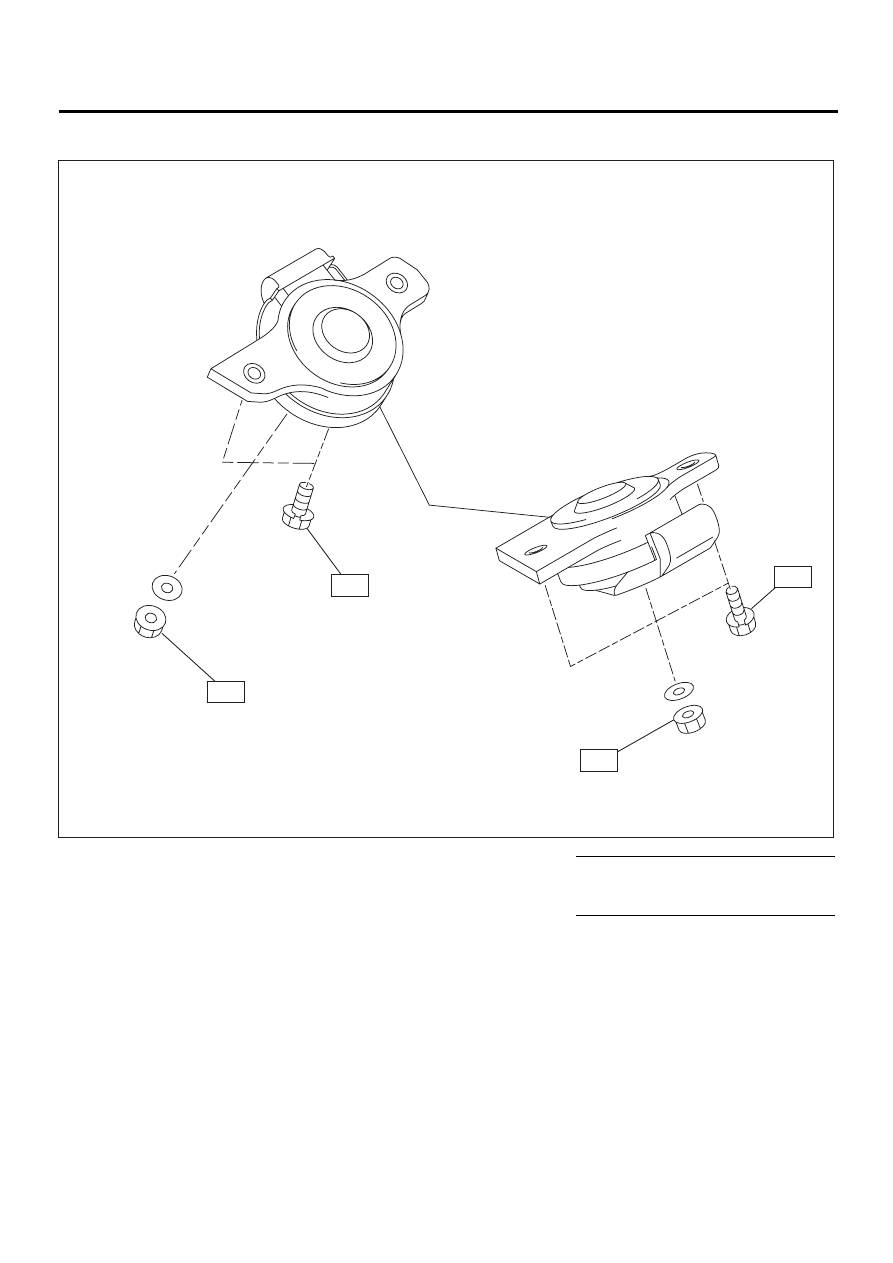
6. ENGINE MOUNTING
(1) Front cushion rubber
Tightening torque: N·m (kgf-m, ft-lb)
T1: 35 (3.5, 25.3)
T2: 85 (8.7, 62.7)
ME-00407
T1
T1
T2
T2
( 1 )
ME(H4DOSTC)-14
MECHANICAL
GENERAL DESCRIPTION
C: CAUTION
• Wear working clothing, including a cap, protec-
tive goggles, and protective shoes during opera-
tion.
• Remove contamination including dirt and corro-
sion before removal, installation or disassembly.
• Keep the disassembled parts in order and pro-
tect them from dust or dirt.
• Before removal, installation or disassembly, be
sure to clarify the failure. Avoid unnecessary re-
moval, installation, disassembly, and replacement.
• Be careful not to burn your hands, because each
part in the vehicle is hot after running.
• Be sure to tighten fasteners including bolts and
nuts to the specified torque.
• Place shop jacks or safety stands at the specified
points.
• Before disconnecting electrical connectors of
sensors or units, be sure to disconnect the ground
cable from battery.
• All parts should be thoroughly cleaned, paying
special attention to the engine oil passages, pis-
tons and bearings.
• Rotating parts and sliding parts such as piston,
bearing and gear should be coated with oil prior to
assembly.
• Be careful not to let oil, grease or coolant contact
the timing belt, clutch disc and flywheel.
• All removed parts, if to be reused, should be re-
installed in the original positions and directions.
• Bolts, nuts and washers should be replaced with
new ones as required.
• Even if necessary inspections have been made
in advance, proceed with assembly work while
making rechecks.
• Remove or install the engine in an area where
chain hoists, lifting devices, etc. are available for
ready use.
• Be sure not to damage coated surfaces of body
panels with tools or stain seats and windows with
coolant or oil. Place a cover over fenders, as re-
quired, for protection.
• Prior to starting work, prepare the following:
Service tools, clean cloth, containers to catch cool-
ant and oil, wire ropes, chain hoist, transmission
jacks, etc.
• Lift-up or lower the vehicle when necessary.
Make sure to support the correct positions.
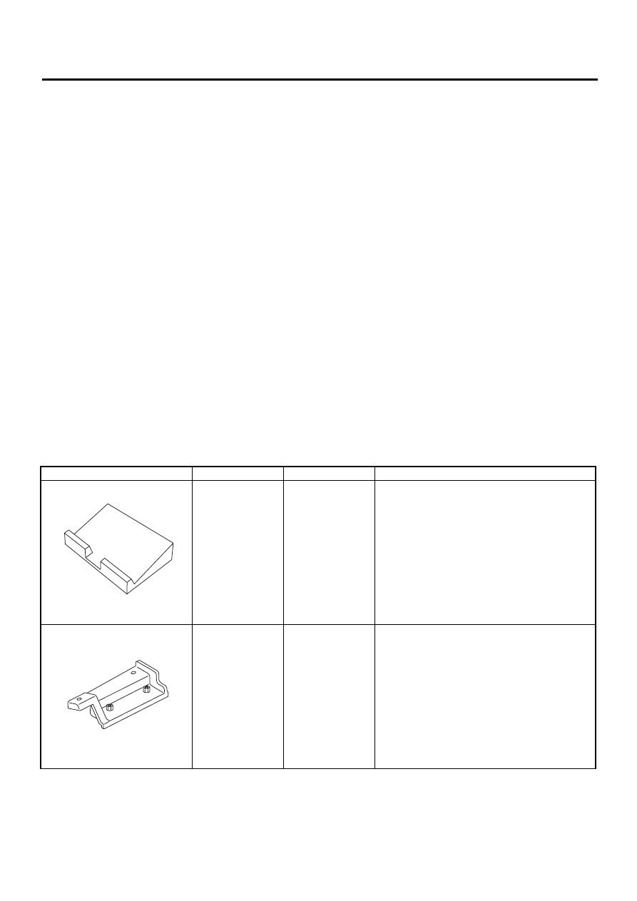
D: PREPARATION TOOL
1. SPECIAL TOOLS
ILLUSTRATION
TOOL NUMBER
DESCRIPTION
REMARKS
498267600
CYLINDER HEAD
TABLE
• Used for replacing valve guides.
• Used for removing and installing valve springs.
498457000
ENGINE STAND
ADAPTER RH
Used with ENGINE STAND (499817000).
ST-498267600
ST-498457000
ME(H4DOSTC)-15
MECHANICAL
GENERAL DESCRIPTION
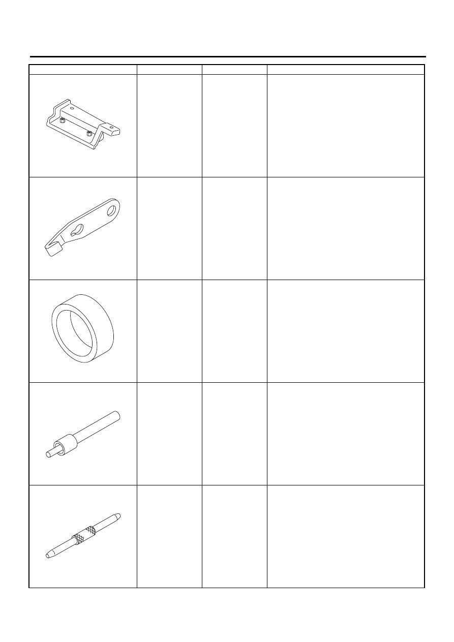
498457100
ENGINE STAND
ADAPTER LH
Used with ENGINE STAND (499817000).
498497100
CRANKSHAFT
STOPPER
Used for stopping rotation of flywheel when loos-
ening and tightening crankshaft pulley bolt, etc.
398744300
PISTON GUIDE
Used for installing piston in cylinder for 2000 cc
engine.
498857100
VALVE OIL SEAL
GUIDE
Used for press-fitting of intake and exhaust valve
guide oil seals.
499017100
PISTON PIN
GUIDE
Used for installing piston pin, piston and connect-
ing rod.
ILLUSTRATION
TOOL NUMBER
DESCRIPTION
REMARKS
ST-498457100
ST-498497100
ST-398744300
ST-498857100
ST-499017100
Нет комментариевНе стесняйтесь поделиться с нами вашим ценным мнением.
Текст