Subaru Legacy III (2000-2003 year). Service manual — part 873
AC-28
HVAC SYSTEM (AUTO A/C) (DIAGNOSTICS)
DIAGNOSTICS FOR A/C SYSTEM FAILURE (LHD MODEL)
11
CHECK POWER SUPPLY TO SUB FAN MO-
TOR.
CAUTION:
Be careful not to overheat engine during re-
pair.
1) Turn ignition switch to OFF.
2) Disconnect connector from sub fan motor.
3) Start the engine, and warm it up until
engine coolant temperature increases over
100
°
C (212
°
F).
4) Stop the engine and turn ignition switch to
ON.
5) Measure voltage between sub fan motor
connector and chassis ground.
Connector & terminal
4 CYLINDER MODEL
(F16) No. 2 (+) — Chassis ground (
−−−−
):
6 CYLINDER MODEL
(F16) No. 1, 2, 3 (+) — Chassis ground
(
−−−−
):
Does the measured value exceed the spec-
ified value?
10 V
Repair harness for
power supply cir-
cuit.
12
CHECK GROUND CIRCUIT OF SUB FAN
MOTOR.
1) Turn ignition switch to OFF.
2) Measure resistance between sub fan motor
connector and chassis ground.
Connector & terminal
4 CYLINDER MODEL
(F16) No. 1 — Chassis ground:
6 CYLINDER MODEL
(F16) No. 4 — Chassis ground:
Does the measured value exceed the spec-
ified value?
1
Ω
Repair harness
between sub fan
motor connector
and chassis
ground.
13
CHECK POOR CONTACT.
Check poor contact in sub fan motor connec-
tor.
Is there poor contact in connector?
There is no poor contact.
Repair poor con-
tact in sub fan
motor connector.
14
CHECK SUB FAN MOTOR.
4 CYLINDER MODEL
Connect battery positive (+) terminal to termi-
nal No. 2, and negative (
−
) terminal to terminal
No. 1 of sub fan motor connector.
6 CYLINDER MODEL
Connect battery positive (+) terminal to termi-
nal No. 1, 2, 3, and negative (
−
) terminal to ter-
minal No. 4 of sub fan motor connector.
Does the sub fan rotate?
Sub fan motor rotates.
Replace sub fan
motor with a new
one.
15
CHECK EACH SENSOR AND POTENTIOME-
TER.
Check the sensors and potentiometer for
proper operation using the self-diagnostic
function. <Ref. to AC-14, OPERATION, Self-
Diagnosis Procedure (LHD Model).>
Is the operation of each sensor and potentiom-
eter normal?
Each sensor and potentiome-
ter operate normally.
Replace sensor
and/or potentiome-
ter.
Step
Value
Yes
No
AC-29
HVAC SYSTEM (AUTO A/C) (DIAGNOSTICS)
DIAGNOSTICS FOR A/C SYSTEM FAILURE (LHD MODEL)
16
CHECK CONNECTION OF ASPIRATOR
DUCT.
Make sure that the connection of aspirator duct
is correct.
Is the connection of duct correct?
There is no poor connection.
Repair aspirator
duct connection.
17
CHECK EACH ACTUATOR.
Check the actuators for proper operation using
the self-diagnostic function.<Ref. to AC-14,
OPERATION, Self-Diagnosis Procedure (LHD
Model).>
Is the operation of each actuator normal?
Actuator operates normally.
Replace actuator.
18
CHECK POOR CONTACT.
Check poor contact in A/C control module.
Is there poor contact in connector?
There is no poor contact.
Replace A/C con-
trol module.
Repair connector.
Step
Value
Yes
No
AC-30
HVAC SYSTEM (AUTO A/C) (DIAGNOSTICS)
DIAGNOSTICS FOR A/C SYSTEM FAILURE (LHD MODEL)
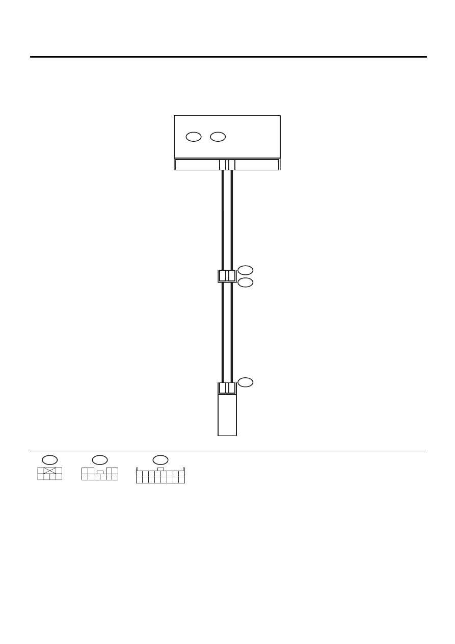
D: FRESH/RECIRC DOES NOT CHANGE
TROUBLE SYMPTOM:
FRESH/RECIRC mode door does not change.
WIRING DIAGRAM:
AC-00365
A7
A15
B91
B201
i40
i49
B:
i48
A:
AUTO A/C
CONTROL MODULE
2
1
INTAKE DOOR
ACTUATOR
7
8
B91
1
3 4 5 6
2
i48
A:
1 2 3 4 5 6 7 8
9 10 11 12 13 14 15 16
i40
1 2
3 4
5 6 7 8 9 10
AC-31
HVAC SYSTEM (AUTO A/C) (DIAGNOSTICS)
DIAGNOSTICS FOR A/C SYSTEM FAILURE (LHD MODEL)
Step
Value
Yes
No
1
CHECK SWITCH OPERATION.
Make sure that the mode selection on display
is changed when pushing the “FRESH/
RECIRC” switch.
Does the mode selection change?
Mode selection changes.
2
CHECK FUSE.
1) Remove No. 17 fuse in fuse & relay box.
2) Check condition of fuse.
Is the fuse blown-out?
Fuse is not blown-out.
Replace fuse.
3
CHECK SIGNAL VOLTAGE.
1) Change display to RECIRC by pushing
FRESH/RECIRC switch.
2) Measure voltage between A/C control mod-
ule and chassis ground.
Connector & terminal
(i48) No. 15 (+) — Chassis ground (
−−−−
):
Is the measured value less than the speci-
fied value?
1 V
Repair short circuit
in harness
between A/C con-
trol module and
intake door actua-
tor.
4
CHECK SIGNAL VOLTAGE.
1) Change display to FRESH with pushing
FRESH/RECIRC switch.
2) Measure voltage between A/C control mod-
ule and chassis ground.
Connector & terminal
(i48) No. 7 (+) — Chassis ground (
−−−−
):
Is the measured value less than the speci-
fied value?
1 V
Repair short circuit
in harness
between A/C con-
trol module and
intake door actua-
tor.
5
CHECK HARNESS CONNECTOR BETWEEN
A/C CONTROL MODULE AND INTAKE
DOOR ACTUATOR.
1) Turn ignition switch to OFF.
2) Disconnect connector from A/C control
module and intake door motor.
3) Measure resistance of harness between A/
C control module and intake door actuator.
Connector & terminal
(i48) No. 15 — (B91) No. 1:
Is the measured value less than the speci-
fied value?
1
Ω
Repair open circuit
in harness
between A/C con-
trol module and
intake door actua-
tor.
6
CHECK HARNESS CONNECTOR BETWEEN
A/C CONTROL MODULE AND INTAKE
DOOR ACTUATOR.
Measure resistance of harness between A/C
control module and intake door actuator.
Connector & terminal
(i48) No. 7 — (B91) No. 2:
Is the measured value less than the specified
value?
1
Ω
Repair open circuit
in harness
between A/C con-
trol module and
intake door actua-
tor.
7
CHECK POOR CONTACT.
Check poor contact in A/C control module con-
nector.
Is there poor contact in connector?
There is no poor contact.
Replace A/C con-
trol module.
Repair connector.
Нет комментариевНе стесняйтесь поделиться с нами вашим ценным мнением.
Текст