Subaru Legacy III (2000-2003 year). Service manual — part 753

VDC-48
VDC (DIAGNOSTICS)
DIAGNOSTICS CHART WITH DIAGNOSIS CONNECTOR
Step
Value
Yes
No
1
CHECK DIAGNOSIS TERMINAL.
Measure resistance between diagnosis termi-
nals (B81) and chassis ground.
Terminals
Diagnosis terminal (A) — Chassis
ground:
Diagnosis terminal (B) — Chassis
ground:
Is the measured value less than the specified
value?
0.5
Ω
Repair diagnosis
terminal harness.
2
CHECK DIAGNOSIS LINE.
1) Turn ignition switch to OFF.
2) Connect diagnosis terminal (B81) to diag-
nosis connector (B82) No. 8.
3) Disconnect connector from VDCCM.
4) Measure resistance between VDCCM con-
nector and chassis ground.
Connector & terminal
(F87) No. 13 — Chassis ground:
Is the measured value less than the speci-
fied value?
0.5
Ω
Repair harness
connector
between VDCCM
and diagnosis con-
nector.
3
CHECK POOR CONTACT IN VDCCM CON-
NECTOR.
Is there poor contact in VDCCM connector?
There is poor contact.
Repair connector.
Replace VDCCM.
<Ref. to VDC-8,
VDC Control Mod-
ule (VDCCM).>
VDC-49
VDC (DIAGNOSTICS)
DIAGNOSTICS CHART WITH DIAGNOSIS CONNECTOR
F: DTC 21 ABNORMAL ABS SENSOR (OPEN CIRCUIT OR INPUT VOLTAGE
TOO HIGH) (FRONT RH)
NOTE:
For diagnostic procedure, refer to DTC 27. <Ref. to VDC-50, DTC 27 ABNORMAL ABS SENSOR (OPEN
CIRCUIT OR INPUT VOLTAGE TOO HIGH) (REAR LH), Diagnostics Chart with Diagnosis Connector.>
G: DTC 23 ABNORMAL ABS SENSOR (OPEN CIRCUIT OR INPUT VOLTAGE
TOO HIGH) (FRONT LH)
NOTE:
For diagnostic procedure, refer to DTC 27. <Ref. to VDC-50, DTC 27 ABNORMAL ABS SENSOR (OPEN
CIRCUIT OR INPUT VOLTAGE TOO HIGH) (REAR LH), Diagnostics Chart with Diagnosis Connector.>
H: DTC 25 ABNORMAL ABS SENSOR (OPEN CIRCUIT OR INPUT VOLTAGE
TOO HIGH) (REAR RH)
NOTE:
For diagnostic procedure, refer to DTC 27. <Ref. to VDC-50, DTC 27 ABNORMAL ABS SENSOR (OPEN
CIRCUIT OR INPUT VOLTAGE TOO HIGH) (REAR LH), Diagnostics Chart with Diagnosis Connector.>
VDC-50
VDC (DIAGNOSTICS)
DIAGNOSTICS CHART WITH DIAGNOSIS CONNECTOR
I:
DTC 27 ABNORMAL ABS SENSOR (OPEN CIRCUIT OR INPUT VOLTAGE
TOO HIGH) (REAR LH)
DIAGNOSIS:
• Faulty ABS sensor (Broken wire, input voltage too high)
• Faulty harness connector
TROUBLE SYMPTOM:
• ABS does not operate.
• VDC does not operate.
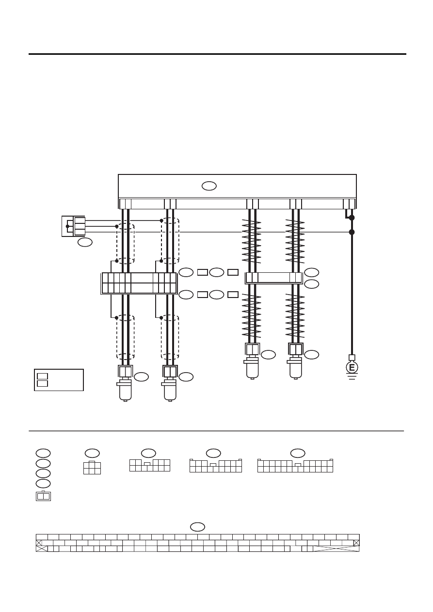
WIRING DIAGRAM:
VDC00174
F55
F88
B15
B6
2 1
R72
R73
F45
F2
1
2
2
1
7
6
2
1
4
1
3
F88
17
15
12
13
16
14
R
10
L
F45
B62
:
:
F2
B100
:
:
F55
R49
B15
R73
49
19
17
16
14
15
1
55
46
18
1
2
B6
2
1
R72
8
9
11
12
13
VDC CONTROL MODULE
FRONT ABS
SENSOR LH
FRONT ABS
SENSOR RH
LHD
RHD
REAR ABS
SENSOR LH
REAR ABS
SENSOR RH
F87
56 57
59 60
62 63
65
82 83
80
27
28
25
26
23
24
21
22
19
20
17
18
15
16
13
14
11
12
9
10
7
8
5
6
3
4
1
2
54
55
52
53
50
51
81
48
49
46
47
44
45
78
79
76
77
75
42
43
40
41
74
72
73
70
71
39
37
38
35
36
69
67
68
66
33
34
61
64
31
32
29
30
58
F87
: RHD MODEL
:LHD MODEL
R
R
R
L
L
L
1
3
4 5 6
2
1 2
3 4 5
6 7 8 9 10 11 12
1 2 3
4 5 6 7
8 9 10 11 12 13 14 15 16
3 4
1 2
8 9 10 11
12 13 14 15 16 17 18 19 20 21 22 23 24
5 6
7

VDC-51
VDC (DIAGNOSTICS)
DIAGNOSTICS CHART WITH DIAGNOSIS CONNECTOR
Step
Value
Yes
No
1
CHECK ABS SENSOR.
1) Turn ignition switch to OFF.
2) Disconnect connector from ABS sensor.
3) Measure resistance of ABS sensor connec-
tor terminals.
Terminal
Front RH No. 1 — No. 2:
Front LH No. 1 — No. 2:
Rear RH No. 1 — No. 2:
Rear LH No. 1 — No. 2:
Is the measured value within the specified
range?
1.0 — 1.5 k
Ω
Replace ABS sen-
sor. Front <Ref. to
VDC-27, Front
ABS Sensor.>
Rear <Ref. to
VDC-28, Rear
ABS Sensor.>
2
CHECK BATTERY SHORT OF ABS SEN-
SOR.
1) Disconnect connector from VDCCM.
2) Measure voltage between ABS sensor and
chassis ground.
Terminal
Front RH No. 1 (+) — Chassis ground (
−−−−
):
Front LH No. 1 (+) — Chassis ground (
−−−−
):
Rear RH No. 1 (+) — Chassis ground (
−−−−
):
Rear LH No. 1 (+) — Chassis ground (
−−−−
):
Is the measured value less than the speci-
fied value?
1 V
Replace ABS sen-
sor. Front <Ref. to
VDC-27, Front
ABS Sensor.>
Rear <Ref. to
VDC-28, Rear
ABS Sensor.>
3
CHECK BATTERY SHORT OF ABS SEN-
SOR.
1) Turn ignition switch to ON.
2) Measure voltage between ABS sensor and
chassis ground.
Terminal
Front RH No. 1 (+) — Chassis ground (
−−−−
):
Front LH No. 1 (+) — Chassis ground (
−−−−
):
Rear RH No. 1 (+) — Chassis ground (
−−−−
):
Rear LH No. 1 (+) — Chassis ground (
−−−−
):
Is the measured value less than the speci-
fied value?
1 V
Replace ABS sen-
sor. Front <Ref. to
VDC-27, Front
ABS Sensor.>
Rear <Ref. to
VDC-28, Rear
ABS Sensor.>
4
CHECK HARNESS/CONNECTOR BETWEEN
VDCCM AND ABS SENSOR.
1) Turn ignition switch to OFF.
2) Connect connector to ABS sensor.
3) Measure resistance between VDCCM con-
nector terminals.
Connector & terminal
DTC 21 / (F87) No. 14 — No. 15:
DTC 23 / (F87) No. 49 — No. 19:
DTC 25 / (F87) No. 18 — No. 46:
DTC 27 / (F87) No. 16 — No. 17:
Is the measured value within the specified
range?
1.0 — 1.5 k
Ω
Repair harness/
connector
between VDCCM
and ABS sensor.
Нет комментариевНе стесняйтесь поделиться с нами вашим ценным мнением.
Текст