Subaru Legacy III (2000-2003 year). Service manual — part 352
EN(H6DO)-210
ENGINE (DIAGNOSTICS)
DIAGNOSTIC PROCEDURE WITH DIAGNOSTIC TROUBLE CODE (DTC)
AP:DTC P0327 — KNOCK SENSOR 1 CIRCUIT LOW INPUT (BANK 1 OR SINGLE
SENSOR) —
• DTC DETECTING CONDITION:
• Immediately at fault recognition
• TROUBLE SYMPTOM:
• Poor driving performance
• Knocking occurs.
CAUTION:
After repair or replacement of faulty parts, conduct Clear Memory Mode <Ref. to EN(H6DO)-54, OP-
ERATION, Clear Memory Mode.> and Inspection Mode <Ref. to EN(H6DO)-47, OPERATION, Inspec-
tion Mode.>.
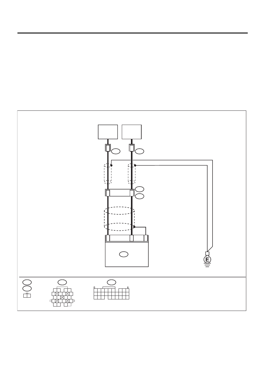
• WIRING DIAGRAM:
EN-00816
4
22
KNOCK
SENSOR
1(RH)
7
2
ECM
B135
B21
E2
E14
B21
E14
1 2
1 2
5
6 7
8
13
14 15
16
9 10
11 12
3 4
17 18
19 20
13
KNOCK
SENSOR
2(LH)
4
2
E48
E48
B135
5 6
7 8
2
1
9
4
3
10
24
22
23
25
11 12 13 14 15
26 27 28
16 17 18 19
20 21

EN(H6DO)-211
ENGINE (DIAGNOSTICS)
DIAGNOSTIC PROCEDURE WITH DIAGNOSTIC TROUBLE CODE (DTC)
Step
Value
Yes
No
1
CHECK HARNESS BETWEEN KNOCK SEN-
SOR 1 AND ECM CONNECTOR.
1) Turn ignition switch to OFF.
2) Disconnect connector from ECM.
3) Measure resistance between ECM harness
connector and chassis ground.
Connector & terminal
(B135) No. 4 — Chassis ground:
Does the measured value exceed the spec-
ified value?
700 k
Ω
Repair harness
and connector.
NOTE:
In this case, repair
the following:
• Open circuit in
harness between
knock sensor 1
(RH) and ECM
connector
• Poor contact in
knock sensor 1
(RH) connector
• Poor contact in
coupling connector
2
CHECK KNOCK SENSOR 1 (RH).
1) Disconnect connector from knock sensor 1
(RH).
2) Measure resistance between knock sensor
connector terminal and engine ground.
Terminal
No. 2 — Engine ground:
Does the measured value exceed the spec-
ified value?
700 k
Ω
Repair harness
and connector.
NOTE:
In this case, repair
the following:
• Open circuit in
harness between
knock sensor 1
(RH) and ECM
connector
• Poor contact in
knock sensor 1
(RH) connector
• Poor contact in
coupling connector
3
CHECK CONDITION OF KNOCK SENSOR 1
(RH) INSTALLATION.
Is the knock sensor 1 (RH) installation bolt
tightened securely?
Tightened securely.
Replace knock
sensor 1 (RH).
<Ref. to
FU(H6DO)-32,
Knock Sensor.>
Tighten knock
sensor 1 (RH)
installation bolt
securely.
EN(H6DO)-212
ENGINE (DIAGNOSTICS)
DIAGNOSTIC PROCEDURE WITH DIAGNOSTIC TROUBLE CODE (DTC)
AQ:DTC P0328 — KNOCK SENSOR 1 CIRCUIT HIGH INPUT (BANK 1 OR SIN-
GLE SENSOR) —
• DTC DETECTING CONDITION:
• Immediately at fault recognition
• TROUBLE SYMPTOM:
• Poor driving performance
• Knocking occurs.
CAUTION:
After repair or replacement of faulty parts, conduct Clear Memory Mode <Ref. to EN(H6DO)-54, OP-
ERATION, Clear Memory Mode.> and Inspection Mode <Ref. to EN(H6DO)-47, OPERATION, Inspec-
tion Mode.>.
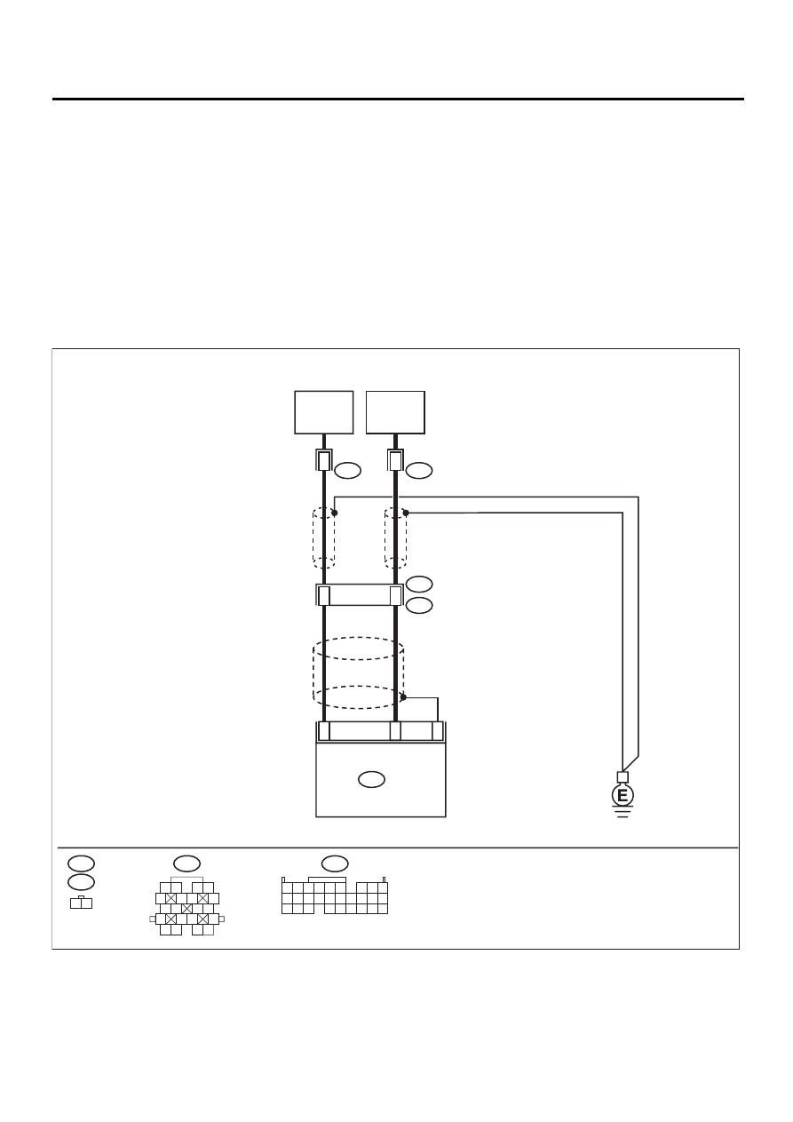
• WIRING DIAGRAM:
EN-00816
4
22
KNOCK
SENSOR
1(RH)
7
2
ECM
B135
B21
E2
E14
B21
E14
1 2
1 2
5
6 7
8
13
14 15
16
9 10
11 12
3 4
17 18
19 20
13
KNOCK
SENSOR
2(LH)
4
2
E48
E48
B135
5 6
7 8
2
1
9
4
3
10
24
22
23
25
11 12 13 14 15
26 27 28
16 17 18 19
20 21

EN(H6DO)-213
ENGINE (DIAGNOSTICS)
DIAGNOSTIC PROCEDURE WITH DIAGNOSTIC TROUBLE CODE (DTC)
Step
Value
Yes
No
1
CHECK HARNESS BETWEEN KNOCK SEN-
SOR 1 (RH) AND ECM CONNECTOR.
Measure resistance of harness between ECM
connector and chassis ground.
Connector & terminal
(B135) No. 4 — Chassis ground:
Is the measured value less than the specified
value?
400 k
Ω
2
CHECK KNOCK SENSOR 1 (RH).
1) Disconnect connector from knock sensor 1
(RH).
2) Measure resistance between knock sensor
connector terminal and engine ground.
Terminal
No. 2 — Engine ground:
Is the measured value less than the speci-
fied value?
400 k
Ω
Replace knock
sensor 1 (RH).
<Ref. to
FU(H6DO)-32,
Knock Sensor.>
Repair ground
short circuit in har-
ness between
knock sensor 1
(RH) connector
and ECM connec-
tor.
NOTE:
The harness be-
tween both con-
nectors is
shielded. Repair
short circuit of har-
ness together with
shield.
3
CHECK INPUT SIGNAL FOR ECM.
1) Connect connectors to ECM and knock
sensor 1 (RH).
2) Turn ignition switch to ON.
3) Measure voltage between ECM and chas-
sis ground.
Connector & terminal
(B135) No. 4 (+) — Chassis ground (
−−−−
):
Does the measured value exceed the spec-
ified value?
2 V
Even if MI lights
up, the circuit has
returned to a nor-
mal condition at
this time. (How-
ever, the possibil-
ity of poor contact
still remains.)
NOTE:
In this case, repair
the following:
• Poor contact in
knock sensor 1
(RH) connector
• Poor contact in
ECM connector
• Poor contact in
coupling connector
Repair poor con-
tact in ECM con-
nector.
Нет комментариевНе стесняйтесь поделиться с нами вашим ценным мнением.
Текст