Subaru Legacy III (2000-2003 year). Service manual — part 999
CC-16
CRUISE CONTROL SYSTEM (DIAGNOSTICS)
DIAGNOSTICS CHART WITH SYMPTOM
C: CHECK CRUISE CONTROL MAIN SWITCH
TROUBLE SYMPTOM:
Cruise control main switch is not turned ON and cruise control cannot be set.
NOTE:
When the main relay (built-in cruise control module) operates, the main switch circuit is in normal condition.
The main relay operation can be checked by hearing the operation sounds.
This operation sounds will be heard when ignition switch and cruise control main switch is turned to ON.
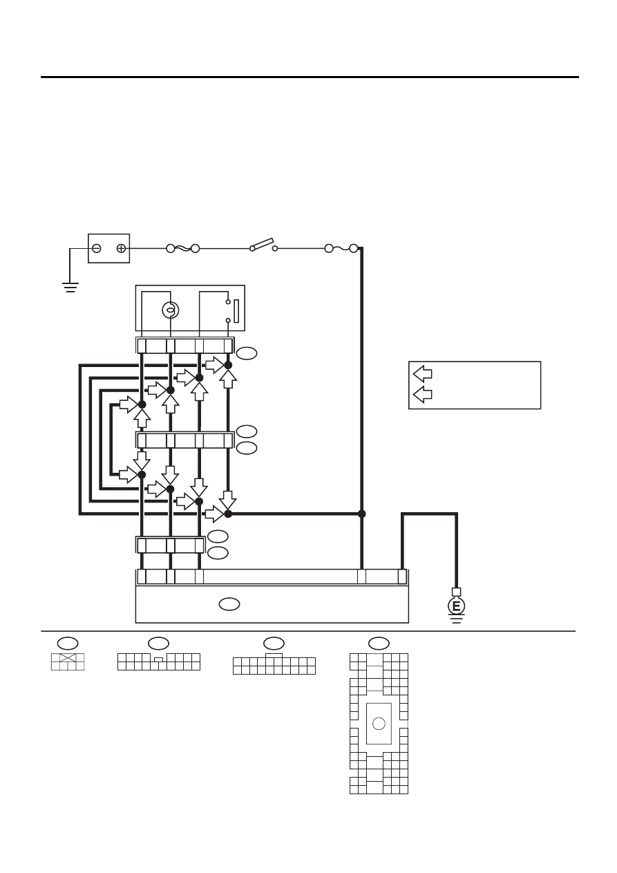
WIRING DIAGRAM:
M2
B2
A2
1
11
15
12
6
i1
B36
CRUISE CONTROL MODULE
B94
BATTERY
IGNITION
SWITCH
6
1
5
3
NO. 18
SBF-4
i19
SMJ
CRUISE CONTROL
MAIN SWITCH
i19
1
3 4 5 6
2
B94
1 2 3 4 5 6 7 8 9 10
11 12 13 14 15 16 17 18 19 20
B36
B4 B5 B6
A4 A5 A6
C5 C6
F6
D4 D5 D6
F1
H1
C4
G6
G1
C2
K1
M1 M2
K6
L1
D1 D2
A1 A2
B1 B2
I6
J6
L2
I1
J1
H6
M4 M5 M6
L4 L5 L6
N5 N6
O4 O5 O6
N4
P4 P5
N2
O1 O2
P1 P2
N3
O3
P3
P6
A3
B3
C3
E4 E5 E6
E1 E2
3
1
11
9
i60
i61
CC-00096
B
A
B
A
B
A
B
A
B
A
B
A
B
A
B
B
A
: LHD H6 AND LHD H4 FOR
EUROPE
: LHD H4 EXCEPT FOR EUROPE
AND RHD
A
B
1 2 3
9 10
4
11 12 13 14 15 16
5 6 7
17 18
8
i60

CC-17
CRUISE CONTROL SYSTEM (DIAGNOSTICS)
DIAGNOSTICS CHART WITH SYMPTOM
Step
Value
Yes
No
1
CHECK CRUISE CONTROL MAIN SWITCH
CIRCUIT.
1) Turn ignition switch OFF.
2) Disconnect cruise control main switch har-
ness connector.
3) Turn ignition switch ON.
4) Measure voltage between harness connec-
tor terminal and chassis ground.
Connector & terminal
(i19) No. 3 (+) — Chassis ground (
−−−−
):
Does the measured value exceed the spec-
ified value?
10 V
• Check fuse No.
18 (in fuse & relay
box).
• Check harness
for open or short
between cruise
control main
switch and fuse &
relay box.
2
CHECK CRUISE CONTROL MAIN SWITCH
CIRCUIT.
1) Turn ignition switch OFF.
2) Disconnect cruise control module harness
connector.
3) Measure resistance between cruise control
module harness connector terminal and
cruise control main switch harness connec-
tor terminal.
Connector & terminal
(B94) No. 15 — (i19) No. 5:
(B94) No. 1 — (i19) No. 6:
(B94) No. 11 — (i19) No. 1:
Is the measured value less than the speci-
fied value?
10
Ω
Repair harness.
3
CHECK CRUISE CONTROL MAIN SWITCH.
Remove and check cruise control main switch.
<Ref. to CC-7, Cruise Control Main Switch.>
Is cruise control main switch OK?
Cruise control main switch is
OK.
Replace cruise
control module.
Replace cruise
control main
switch.
CC-18
CRUISE CONTROL SYSTEM (DIAGNOSTICS)
DIAGNOSTICS CHART WITH SYMPTOM
D: CHECK CRUISE CONTROL COMMAND SWITCH
TROUBLE SYMPTOM:
Cruise control cannot be set. (Cancelled immediately.)
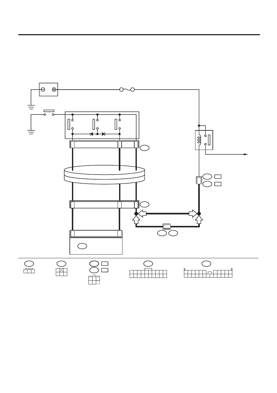
WIRING DIAGRAM:
CC-00097
3
2
1
9
10
F2
CRUISE CONTROL
MODULE
B94
BATTERY
5
M/B NO. 6
S1
B100
B94
1 2 3 4 5 6 7 8 9 10
11 12 13 14 15 16 17 18 19 20
F2
RESUME/
ACCEL
SWITCH
CANCEL
SWITCH
SET/
COAST
SWITCH
HORN SWITCH
4
B68
HORN RELAY
STEERING ROLL
CONNECTOR
HORN
S1
F37
4
1 2 3
6
5
B68
4
1
2
3
5
3
2
1
3
2
1
RHD
RHD
LHD
LHD
CRUISE CONTROL
COMMAND SWITCH
F37
LHD
:
B144
RHD
:
F37
LHD
:
B144
RHD
:
1 2 3 4 5 6
9
7 8
10
12 13 14 15 16
22 23
11
24
17 18 19
21
20

CC-19
CRUISE CONTROL SYSTEM (DIAGNOSTICS)
DIAGNOSTICS CHART WITH SYMPTOM
Step
Value
Yes
No
1
CHECK SET/COAST SWITCH CIRCUIT.
1) Turn ignition switch OFF.
2) Disconnect cruise control module harness
connector.
3) Measure voltage between harness connec-
tor terminal and chassis ground when SET/
COAST switch is pressed and not pressed.
Connector & terminal
(B94) No. 10 (+) — Chassis ground (
−−−−
):
Is the measured value less than the speci-
fied value, when SET/COAST switch is not
pressed?
Does the measured value exceed the spec-
ified value, when SET/COAST switch is
pressed?
When SET/COAST switch is
not pressed: 0 V, and when
SET/COAST switch is
pressed: 10 V
2
CHECK RESUME/ACCEL SWITCH CIRCUIT.
Measure voltage between harness connector
terminal and chassis ground when RESUME/
ACCEL switch is pressed and not pressed.
Connector & terminal
(B94) No. 9 (+) — Chassis ground (
−−−−
):
Is the measured value less than the specified
value, when RESUME/ACCEL switch is not
pressed?
Does the measured value exceed the specified
value, when RESUME/ACCEL switch is
pressed?
When RESUME/ACCEL
switch is not pressed: 0 V, and
when RESUME/ACCEL switch
is pressed: 10 V
3
CHECK CANCEL SWITCH CIRCUIT.
Measure voltage between harness connector
terminal and chassis ground when CANCEL
switch is pressed and not pressed.
Connector & terminal
(B94) No. 9 (+) — Chassis ground (
−−−−
):
(B94) No. 10 (+) — Chassis ground (
−−−−
):
Is the measured value less than the specified
value, when CANCEL switch is not pressed?
Does the measured value exceed the specified
value, when CANCEL switch is pressed?
When CANCEL switch is not
pressed: 0 V, and when CAN-
CEL switch is pressed: 10 V
Cruise control
command switch
circuit is OK.
4
CHECK POWER SUPPLY FOR COMMAND
SWITCH.
Check horn operation.
Does horn sound?
Horn sounds.
• Check fuse No.
6 (in main fuse
box).
• Check horn
relay. <Ref. to
COM-3, HORN
RELAY, INSPEC-
TION, Horn Sys-
tem.>
• Check harness
for open or short
between cruise
control command
switch and fuse &
relay box.
5
CHECK CRUISE CONTROL COMMAND
SWITCH.
Remove and check cruise control command
switch. <Ref. to CC-8, Cruise Control Com-
mand Switch.>
Is cruise control command switch OK?
Cruise control command
switch is OK.
Check harness
between cruise
control command
switch and cruise
control module.
Replace cruise
control command
switch.
Нет комментариевНе стесняйтесь поделиться с нами вашим ценным мнением.
Текст