Subaru Legacy III (2000-2003 year). Service manual — part 626
MT-72
MANUAL TRANSMISSION AND DIFFERENTIAL
MAIN SHAFT ASSEMBLY FOR SINGLE-RANGE
6) Using ST1 and ST2, install the 5th gear thrust
washer and 5th needle bearing race onto the rear
section of transmission main shaft.
NOTE:
• Do not apply pressure in excess of 10 kN (1 ton,
1.1 US ton, 1.0 Imp ton).
• Face thrust washer in the correct direction.
ST1
899714110
REMOVER
ST2
499877000
RACE 4-5 INSTALLER
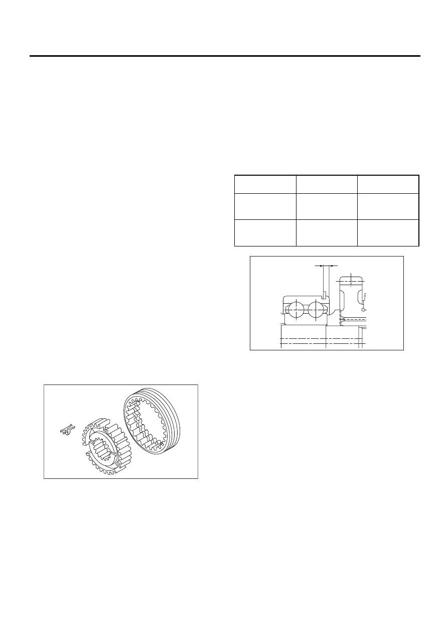
7) Install bearing onto synchro cone.
8) Install baulk ring and synchro cone onto 5th-Rev
sleeve and hub assembly using ST and a press.
NOTE:
• Do not apply pressure in excess of 10 kN (1 ton,
1.1 US ton, 1.0 Imp ton).
• Use new ball bearing.
• After press fitting, make sure synchro cone ro-
tates freely.
ST
499757002
INSTALLER
9) Install synchro cone stopper and snap ring to
5th-Rev sleeve and hub assembly.
10) Install the rest parts to the rear section of trans-
mission main shaft.
NOTE:
Align groove in baulk ring with shifting insert.
11) Tighten lock nuts to the specified torque using
ST1 and ST2.
NOTE:
Secure lock nuts in two places after tightening.
ST1
499987003
SOCKET WRENCH
ST2
498937000
TRANSMISSION HOLDER
Tightening torque:
120 N·m (12.2 kgf-m, 88.2 ft-lb)
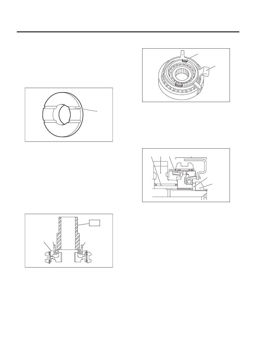
(A) Face this surface to 5th gear side.
(A) Baulk ring
(B) Synchro cone
(C) Ball bearing
MT-00195
( A )
MT-00196
( A ) ( B )
( C )
ST
(A) Synchro cone stopper
(B) Snap ring
(A) Needle bearing
(B) 5th drive gear
(C) Baulk ring
(D) 5th-Rev sleeve and hub ASSY
(E) Lock washer
(F) Lock nuts
MT-00188
( A )
( B )
MT-00198
( A )
( B ) ( C )
( D )
( E )
( F )
MT-73
MANUAL TRANSMISSION AND DIFFERENTIAL
MAIN SHAFT ASSEMBLY FOR SINGLE-RANGE
E: INSPECTION
Disassembled parts should be washed clean first
and then inspected carefully.
1) Bearings
Replace bearings in the following cases:
• Bearings whose balls, outer races and inner rac-
es are broken or rusty.
• Worn bearings
• Bearings that fail to turn smoothly or make ab-
normal noise when turned after gear oil lubrication.
• Bearings having other defects
2) Bushing (each gear)
Replace the bushing in the following cases:
• When the sliding surface is damaged or abnor-
mally worn.
• When the inner wall is abnormally worn.
3) Gears
• Replace gears with new ones if their tooth sur-
faces are broken, damaged, or excessively worn.
• Correct or replace if the cone that contacts the
baulk ring is rough or damaged.
• Correct or replace if the inner surface or end face
is damaged.
4) Baulk ring
Replace the ring in the following cases:
• When the inner surface and end face are dam-
aged.
• When the ring inner surface is abnormally or par-
tially worn down.
• When the contact surface of the synchronizer
ring insert is scored or abnormally worn down.
5) Shifting insert key
Replace the insert if deformed, excessively worn,
or defective in any way.
6) Oil seal
Replace the oil seal if the lip is deformed, hard-
ened, damaged, worn, or defective in any way.
7) O-ring
Replace the O-ring if the sealing face is deformed,
hardened, damaged, worn, or defective in any
way.
8) Gearshift mechanism
Repair or replace the gearshift mechanism if ex-
cessively worn, bent, or defective in any way.
F: ADJUSTMENT
Selection of main shaft rear plate
Using ST, measure the amount (A) of ball bearing
protrusion from transmission main case surface
and select the proper plate in the following table:
NOTE:
Before measuring, tap the end of main shaft with a
plastic hammer lightly in order to make the clear-
ance zero between the main case surface and the
moving flange of bearing.
ST
498147000
DEPTH GAUGE
MT-00208
Dimension (A)
mm (in)
Part No.
Mark
4.00 — 4.13
(0.1575 —
0.1626)
32294AA041
1
3.87 — 3.99
(0.1524 —
0.1571)
32294AA051
2
MT-00209
( A )
MT-74
MANUAL TRANSMISSION AND DIFFERENTIAL
MAIN SHAFT ASSEMBLY FOR DUAL-RANGE
16.Main Shaft Assembly for
Dual-Range
A: REMOVAL
1) Remove the manual transmission assembly
from vehicle. <Ref. to MT-32, REMOVAL, Manual
Transmission Assembly.>
2) Remove transfer case with extension case as-
sembly. <Ref. to MT-47, REMOVAL, Transfer
Case and Extension Case Assembly.>
3) Remove transmission case. <Ref. to MT-47, RE-
MOVAL, Transfer Case and Extension Case As-
sembly.>
4) Removes drive pinion shaft assembly. <Ref. to
MT-87, REMOVAL, Drive Pinion Shaft Assembly.>
5) Remove main shaft assembly and input shaft as-
sembly.
B: INSTALLATION
1) Install the needle bearing onto the front of trans-
mission main shaft assembly.
2) Connect main shaft assembly and input shaft as-
sembly.
3) Install needle bearing outer race knock pin hole
into transmission case knock pin.
4) Install the drive pinion assembly. <Ref. to MT-
87, INSTALLATION, Drive Pinion Shaft Assem-
bly.>
5) Install transmission case. <Ref. to MT-61, IN-
STALLATION, Transmission Case.>
6) Install transfer case with extension case assem-
bly. <Ref. to MT-47, INSTALLATION, Transfer
Case and Extension Case Assembly.>
7) Install the manual transmission assembly to ve-
hicle. <Ref. to MT-35, INSTALLATION, Manual
Transmission Assembly.>
C: DISASSEMBLY
1) Put vinyl tape around main shaft splines to pro-
tect oil seal from damage. Then pull out oil seal
and needle bearing by hand.
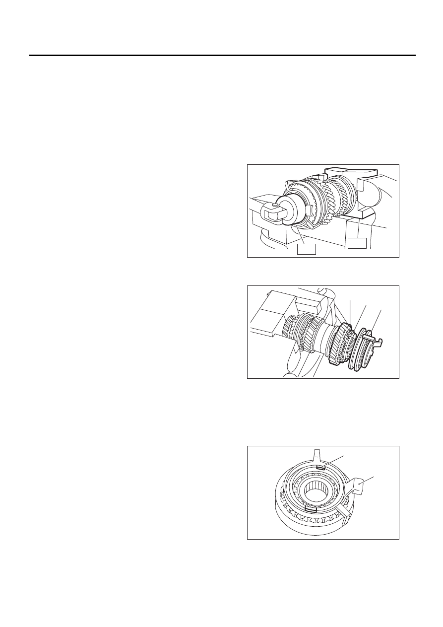
2) Remove lock nut from transmission main shaft
assembly.
NOTE:
Remove caulking before taking off lock nut.
ST1
498937000
TRANSMISSION HOLDER
ST2
499987003
SOCKET WRENCH (35)
3) Remove 5th-Rev sleeve and hub assembly,
baulk ring, 5th drive gear and needle bearing.
4) Remove snap ring and synchro cone stopper
from 5th-Rev sleeve and hub assembly.
(A) 5th-Rev sleeve and hub ASSY
(B) Baulk ring
(C) 5th drive gear
(A) Synchro cone stopper
(B) Snap ring
MT-00186
ST2
ST1
MT-00187
( A )
( B )
( C )
MT-00188
( A )
( B )
MT-75
MANUAL TRANSMISSION AND DIFFERENTIAL
MAIN SHAFT ASSEMBLY FOR DUAL-RANGE
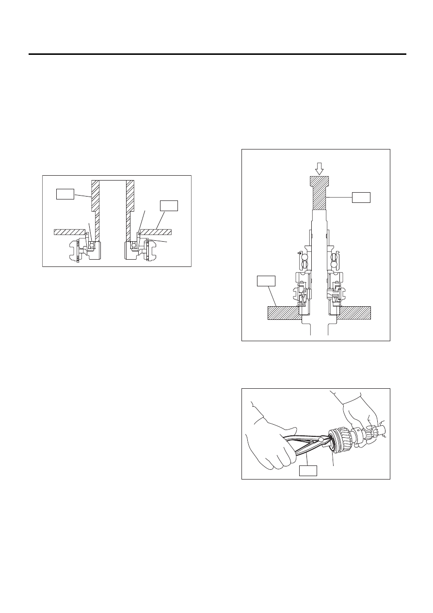
5) Using ST1, ST2 and a press, remove ball bear-
ing, synchro cone and baulk ring (Rev).
NOTE:
• Replace sleeve and hub with new ones. Do not
attempt to disassemble because they must engage
at a specified point. If they should be disassem-
bled, mark engagement point on splines before-
hand.
• Do not reuse ball bearing.
ST1
499757002
INSTALLER
ST2
498077400
SYNCHRO CONE REMOV-
ER
6) Using ST1 and ST2, remove the rest of parts.
NOTE:
Replace sleeve and hub with new ones. Do not at-
tempt to disassemble because they must engage
at a specified point. If they should be disassem-
bled, marking engagement point on splines before-
hand.
ST1
899864100
REMOVER
ST2
899714110
REMOVER
7) Remove snap ring from main shaft.
ST
899474100
EXPANDER
(A) Ball bearing
(B) Synchro cone
(C) Baulk ring
MT-00189
( A )
( B )
( C )
ST1
ST2
(A) Press
(A) Snap ring
MT-00190
ST1
ST2
( A )
MT-00215
( A )
ST
Нет комментариевНе стесняйтесь поделиться с нами вашим ценным мнением.
Текст