Subaru Legacy III (2000-2003 year). Service manual — part 954
IDI-16
INSTRUMENTATION/DRIVER INFO
COMBINATION METER ASSEMBLY
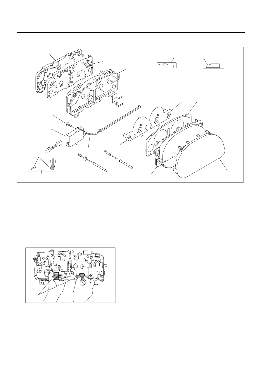
2. LUMINESCENT METER
1) Remove screw (K) and disconnect connectors,
detach CFL (Cold Cathode Fluorescent Light) in-
verter (J).
2) Unfasten CFL harness (I) from back cover
groove.
3) Disengage claw (M) to remove meter glass (F),
reflector (G), and window plate (E) from case (C).
4) Remove connector cover and release connector
lock by pulling both end of it, disconnect FPC (Flex-
ible Printed Circuit) connector (P).
5) Pull up claw (N) on back cover (A) with combina-
tion pliers.
6) Push out speedometer assembly (H) and ta-
chometer assembly (D) using hole (O).
7) Disengage claw (L) to remove case (C) from
back cover (A).
8) Pull up claw in center of printed circuit (B), re-
move printed circuit from case (C).
IDI00049
( A )
( B )
( C )
( D )
( E )
( F )
( G )
( H )
( I )
( J )
( K )
( L )
( M )
( N )
( O )
IDI00050
( P )
IDI-17
INSTRUMENTATION/DRIVER INFO
COMBINATION METER ASSEMBLY
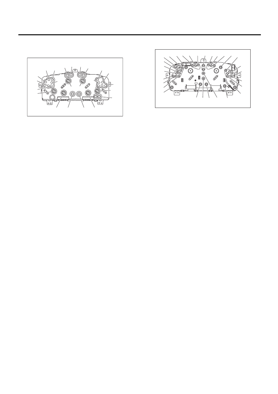
3. BULB REPLACEMENT
• Standard meter:
• Luminescent meter:
D: ASSEMBLY
Assemble in the reverse order of disassembly.
(1) Tachometer and water temperature gauge
(2) ABS
(3) VDC
(4) Oil pressure
(5) Charge
(6) AT oil temp.
(7) Check engine
(8) HI-beam
(9) Turn RH
(10) Tachometer
(11) Turn LH
(12) Brake
(13) Speedometer
(14) VDC function
(15) 4WD LO
(16) FWD
(17) VDC OFF
(18) Airbag
(19) Speedometer and fuel gauge
(20) Low fuel
(21) LCD
(22) POWER
(23) HOLD
(24) LCD
IDI00031
( 1 )
( 2 )
( 3 )
( 4 )
( 5 ) ( 6 )
( 7 )
( 8 ) ( 9 )
(10)
(11)
(12)
(13)
(14)
(15)
(16)
(17)
(18)
(19)
(20)
(21)
(22)
(23)
(24)
(1) Water temperature gauge ring
(2) Tachometer and water temperature gauge ring
(3) ABS
(4) VDC
(5) Oil pressure
(6) Check engine
(7) Charge
(8) AT oil temp.
(9) Lighting switch
(10) Tachometer ring
(11) HI-beam
(12) Turn RH
(13) HOLD
(14) LCD
(15) POWER
(16) Turn LH
(17) Brake
(18) Speedometer ring
(19) VDC function
(20) AIRBAG
(21) FWD
(22) VDC OFF
(23) Speedometer and fuel gauge ring
(24) Fuel gauge ring
(25) Low fuel
(26) AT select lever position (P)
(27) Speedometer ring
(28) AT select lever position (D)
(29) Tachometer ring
PP
>PP<
SAE
IDI00051
( 1 )
( 2 )
( 3 )
( 4 )
( 5 )
( 6 )
( 7 )
( 8 )
( 9 ) (10) (11) (12) (13) (14) (15) (16) (17) (18) (19)
(20)
(21)
(22)
(23)
(24)
(25)
(26)
(27)
(28)
(29)
IDI-18
INSTRUMENTATION/DRIVER INFO
SPEEDOMETER
4. Speedometer
A: REMOVAL
Disassemble combination meter, and then remove
speedometer and fuel gauge assembly. <Ref. to
IDI-15, DISASSEMBLY, Combination Meter As-
sembly.>
B: INSTALLATION
Install in the reverse order of removal.
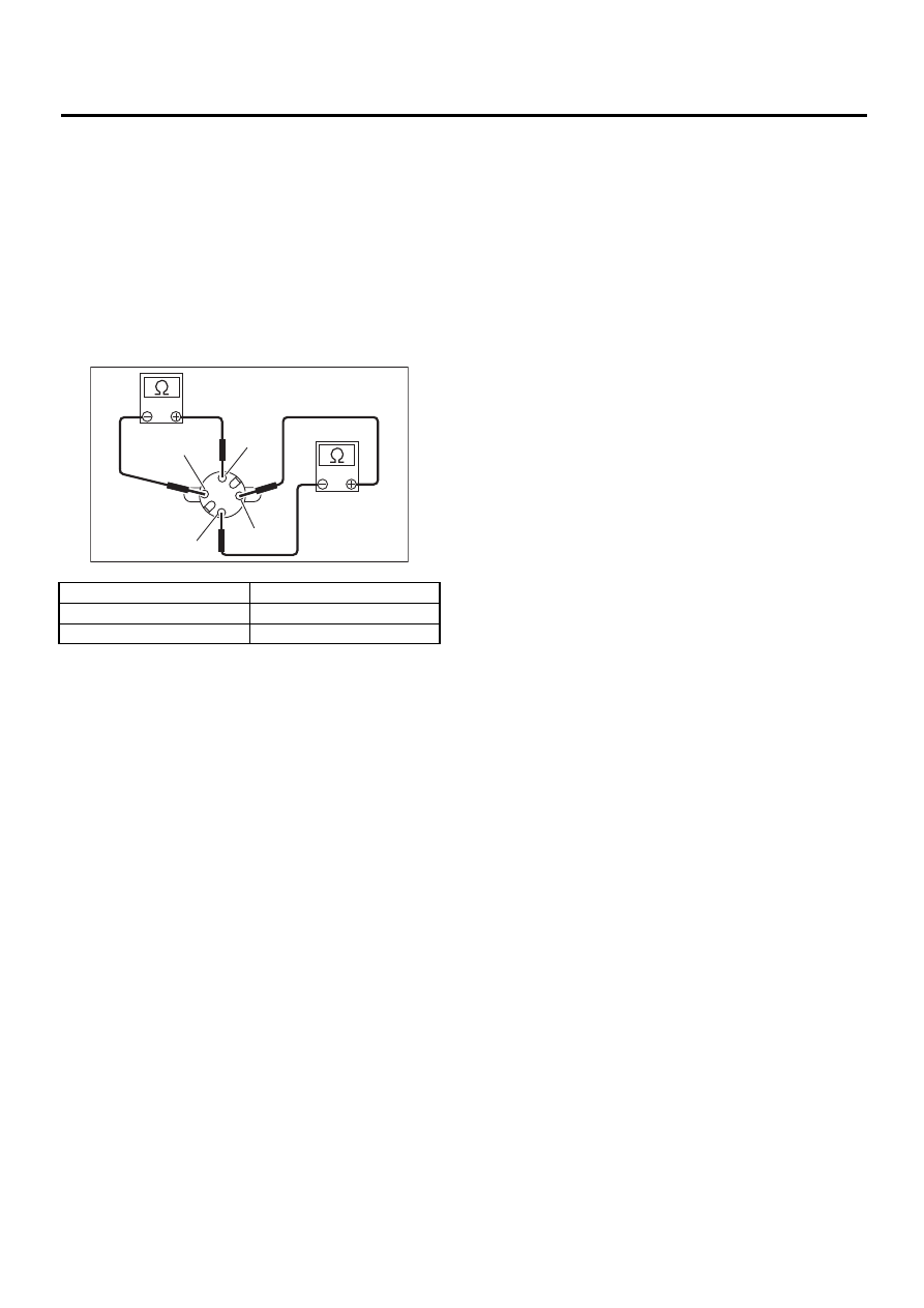
C: INSPECTION
Measure speedometer resistance.
If NG, replace speedometer and fuel gauge assem-
bly.
If OK, replace combination meter printed circuit.
Terminal
Resistance
Terminals SIN+ and SIN
−
200
±
8
Ω
Terminals COS+ and COS
−
200
±
8
Ω
IDI00032
COS+
SIN+
COS–
SIN–

IDI-19
INSTRUMENTATION/DRIVER INFO
TACHOMETER
5. Tachometer
A: REMOVAL
Disassemble combination meter, and then remove
tachometer and water temperature gauge assem-
bly. <Ref. to IDI-15, DISASSEMBLY, Combination
Meter Assembly.>
B: INSTALLATION
Install in the reverse order of removal.
C: INSPECTION
Measure tachometer resistance.
If NG, replace tachometer and water temperature
gauge assembly.
If OK, replace combination meter printed circuit.
Terminal
Resistance
Terminals SIN+ and SIN
−
200
±
8
Ω
Terminals COS+ and COS
−
200
±
8
Ω
IDI00032
COS+
SIN+
COS–
SIN–
Нет комментариевНе стесняйтесь поделиться с нами вашим ценным мнением.
Текст