Subaru Legacy III (2000-2003 year). Service manual — part 155
EN(H4SO)-232
ENGINE (DIAGNOSTICS)
DIAGNOSTIC PROCEDURE WITH DIAGNOSTIC TROUBLE CODE (DTC)
BA:DTC P0519 — IDLE AIR CONTROL CIRCUIT SYSTEM PERFORMANCE —
• DTC DETECTING CONDITION:
• Immediately at fault recognition
• TROUBLE SYMPTOM:
• Engine keeps running at higher revolution than specified idling revolution.
CAUTION:
After repair or replacement of faulty parts, conduct Clear Memory Mode<Ref. to EN(H4SO)-47, OPER-
ATION, Clear Memory Mode.> and Inspection Mode <Ref. to EN(H4SO)-40, OPERATION, Inspection
Mode.> .
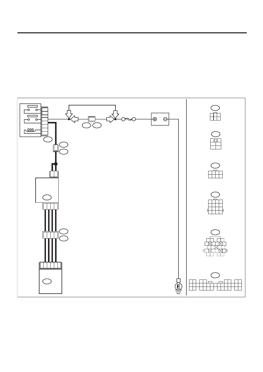
• WIRING DIAGRAM:
EN-01134
F44
B61
6
RHD
RHD
20
6
5
19
B21
E2
ECM
2
5
6
3
4
1
3
4
1
2
IDLE
AIR CONTROL
SOLENOID
VALVE
E7
B22
E3
B47
B134
B47
3
4
1
2
5
6
B134
1 2
3 4
5 6
7 8
9 10 11 12 13 14 15 16 17 18 19 20 21 22 23
24 25
26 27 28 29
30 31 32 33
34 35
B22
1 2 3 4
5 6 7 8
9 10 11 12
13 14 15 16
E7
1
3
4 5 6
2
B21
1 2
3 4
5
6 7
8
9 10
11 12
13
14 15
16
17 18
19 20
SBF-5
BATTERY
MAIN RELAY
1
2
3
5
4
6
1
1 2 3 4
5 6 7 8
F44
LHD
LHD

EN(H4SO)-233
ENGINE (DIAGNOSTICS)
DIAGNOSTIC PROCEDURE WITH DIAGNOSTIC TROUBLE CODE (DTC)
Step
Value
Yes
No
1
CHECK ANY OTHER DTC ON DISPLAY.
Is any other DTC displayed?
DTC indicated.
Inspect the rele-
vant DTC using
“List of Diagnostic
Trouble Code
(DTC)”. <Ref. to
EN(H4SO)-83, List
of Diagnostic
Trouble Code
(DTC).>
NOTE:
In this case, it is
not necessary to
inspect DTC
P0519.
2
CHECK AIR INTAKE SYSTEM.
1) Turn ignition switch to ON.
2) Start engine, and idle it.
3) Check the following items.
•Loose installation of intake manifold, idle air
control solenoid valve and throttle body
•Cracks of intake manifold gasket, idle air con-
trol solenoid valve gasket and throttle body
gasket
•Disconnections of vacuum hoses
Is there a fault in air intake system?
There is a fault.
Repair air suction
and leaks.
3
CHECK THROTTLE CABLE.
Does throttle cable have play for adjustment?
Throttle cable has play for
adjustment.
Adjust throttle
cable. <Ref. to
SP(H4SO)-10,
Accelerator Con-
trol Cable.>
4
CHECK AIR BY-PASS LINE.
1) Turn ignition switch to OFF.
2) Remove idle air control solenoid valve from
throttle body. <Ref. to FU(H4SO)-34,
REMOVAL, Idle Air Control Solenoid
Valve.>
3) Confirm that there are no foreign particles
in by-pass air line.
Are foreign particles in by-pass air line?
Foreign particles are in by-
pass air line.
Remove foreign
particles from by-
pass air line.
Replace idle air
control solenoid
valve. <Ref. to
FU(H4SO)-34, Idle
Air Control Sole-
noid Valve.>
EN(H4SO)-234
ENGINE (DIAGNOSTICS)
DIAGNOSTIC PROCEDURE WITH DIAGNOSTIC TROUBLE CODE (DTC)
BB:DTC P0565 — CRUISE CONTROL ON SIGNAL —
• DTC DETECTING CONDITION:
• Two consecutive driving cycles with fault
CAUTION:
After repair or replacement of faulty parts, conduct Clear Memory Mode<Ref. to EN(H4SO)-47, OPER-
ATION, Clear Memory Mode.> and Inspection Mode <Ref. to EN(H4SO)-40, OPERATION, Inspection
Mode.> .
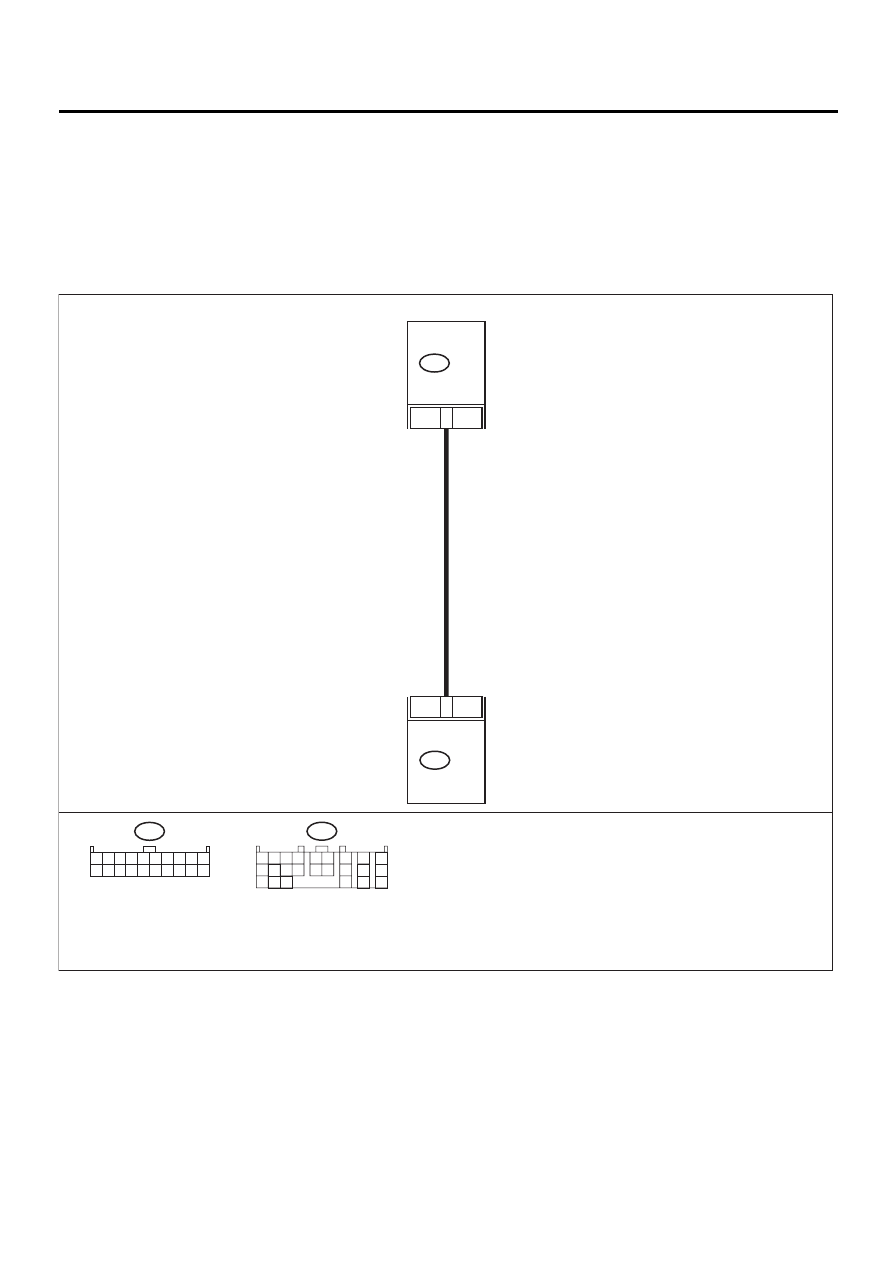
• WIRING DIAGRAM:
EN-01135
CCM
3
22
B94
TCM
B55
B94
1 2 3 4 5 6 7 8 9 10
11 12 13 14 15 16 17 18 19 20
B55
1 2 3 4
10 11 12
19 20 21
13
5 6
14 15
7
8
9
16
17
18
22
23
24

EN(H4SO)-235
ENGINE (DIAGNOSTICS)
DIAGNOSTIC PROCEDURE WITH DIAGNOSTIC TROUBLE CODE (DTC)
Step
Value
Yes
No
1
CHECK HARNESS BETWEEN TCM AND
CCM CONNECTOR.
1) Turn ignition switch to OFF.
2) Disconnect connectors from TCM and
CCM.
3) Measure resistance of harness between
TCM and CCM connector.
Connector & terminal
(B55) No. 22 - (B94) No. 3:
Is the measured value less than the speci-
fied value?
1
Ω
Repair open circuit
in harness
between TCM and
CCM connector.
2
CHECK HARNESS BETWEEN TCM AND
CCM CONNECTOR.
Measure resistance of harness between TCM
and chassis ground.
Connector & terminal
(B55) No. 22 - Chassis ground:
Does the measured value exceed the specified
value?
1 M
Ω
Repair short circuit
in harness
between TCM and
CCM connector.
3
CHECK INPUT SIGNAL FOR TCM.
1) Connect connector to TCM and CCM.
2) Lift-up the vehicle or set the vehicle on free
rollers.
CAUTION:
On AWD models, raise all wheels off
ground.
3) Start the engine.
4) Cruise control main switch to ON.
5) Move selector lever to “D” and slowly
increase vehicle speed to 50 km/h (31
MPH).
6) Cruise control command switch to ON.
7) Measure voltage between TCM and chas-
sis ground.
Connector & terminal
(B55) No. 22 - Chassis ground:
Is the measured value less than the speci-
fied value?
1 V
Check cruise con-
trol command
switch circuit.
<Ref. to CC-8,
INSPECTION,
Cruise Control
Command
Switch.>
4
CHECK POOR CONTACT.
Check poor contact in TCM connector.
Is there poor contact in TCM connector?
There is poor contact.
Repair poor con-
tact in TCM con-
nector.
Replace TCM.
<Ref. to AT-76,
Transmission Con-
trol Module
(TCM).>
Нет комментариевНе стесняйтесь поделиться с нами вашим ценным мнением.
Текст