Subaru Legacy III (2000-2003 year). Service manual — part 339

EN(H6DO)-158
ENGINE (DIAGNOSTICS)
DIAGNOSTIC PROCEDURE WITH DIAGNOSTIC TROUBLE CODE (DTC)
U: DTC P0129 — BAROMETRIC PRESSURE TOO LOW —
• DTC DETECTING CONDITION:
• Two consecutive driving cycles with fault
CAUTION:
After repair or replacement of faulty parts, conduct Clear Memory Mode <Ref. to EN(H6DO)-54, OP-
ERATION, Clear Memory Mode.> and Inspection Mode <Ref. to EN(H6DO)-47, OPERATION, Inspec-
tion Mode.>.
Step
Value
Yes
No
1
CHECK ANY OTHER DTC ON DISPLAY.
Is any other DTC displayed?
Another DTC is displayed.
Inspect the rele-
vant DTC using
“List of Diagnostic
Trouble Code
(DTC)”. <Ref. to
EN(H6DO)-89, List
of Diagnostic
Trouble Code
(DTC).>
Replace ECM.
<Ref. to
FU(H6DO)-46,
Engine Control
Module.>
NOTE:
Atmospheric pres-
sure sensor is built
into ECM.
EN(H6DO)-159
ENGINE (DIAGNOSTICS)
DIAGNOSTIC PROCEDURE WITH DIAGNOSTIC TROUBLE CODE (DTC)
MEMO:
EN(H6DO)-160
ENGINE (DIAGNOSTICS)
DIAGNOSTIC PROCEDURE WITH DIAGNOSTIC TROUBLE CODE (DTC)
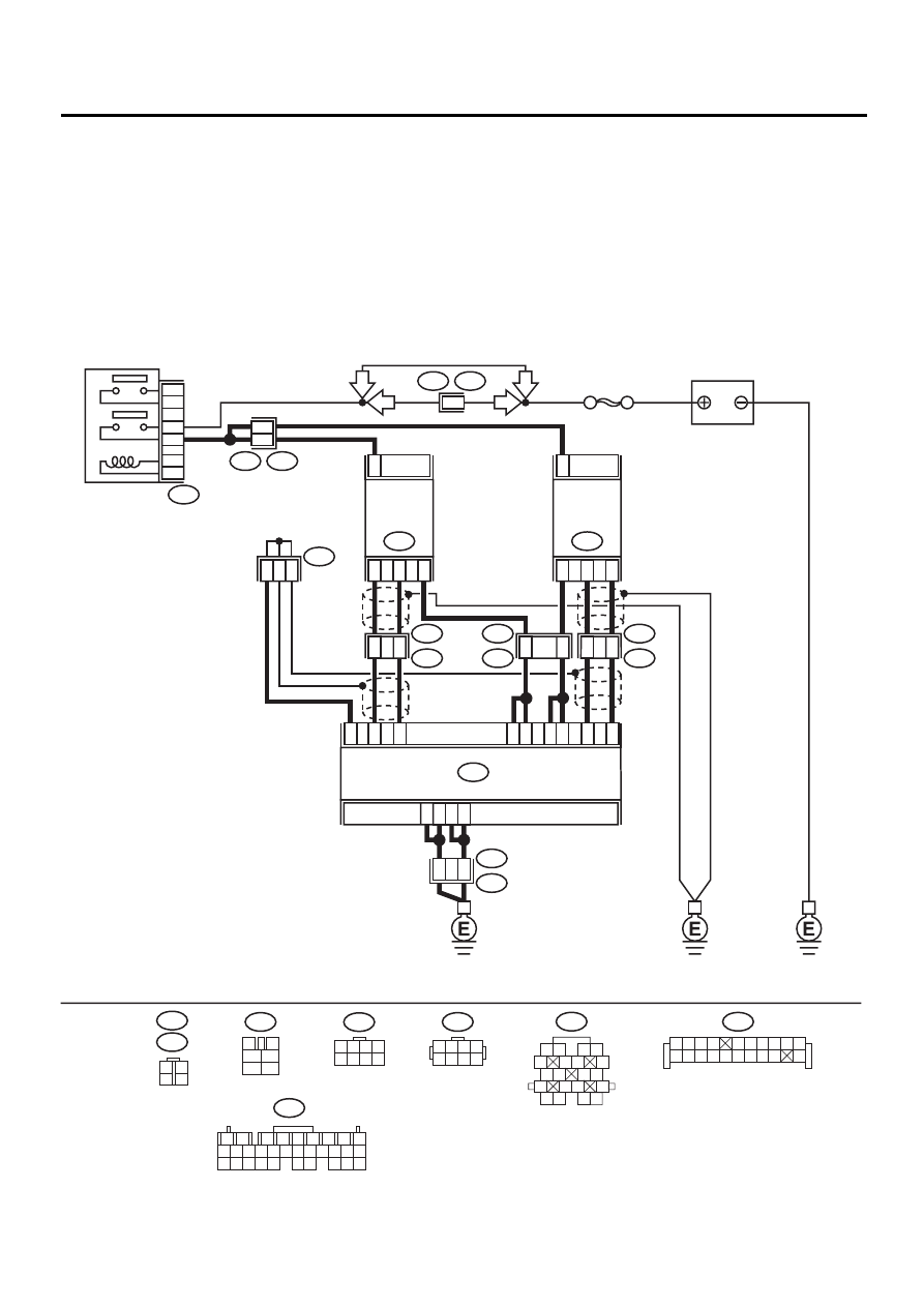
V: DTC P0130 — O2 SENSOR CIRCUIT (BANK 1 SENSOR 1) —
• DTC DETECTING CONDITION:
• Immediately at fault recognition
CAUTION:
After repair or replacement of faulty parts, conduct Clear Memory Mode <Ref. to EN(H6DO)-54, OP-
ERATION, Clear Memory Mode.> and Inspection Mode <Ref. to EN(H6DO)-47, OPERATION, Inspec-
tion Mode.>.
• WIRING DIAGRAM:
EN-01087
BATTERY
F44
B61
SBF-5
6
B47
MAIN RELAY
1
2
3
5
4
6
9
8
21
31
2
1
5
B252
E49
ECM
18
29
19
5
4
7
6
20
30
4
1
3
FRONT
OXYGEN
(A/F)
SENSOR RH
E47
2
4
3
1
FRONT
OXYGEN
(A/F)
SENSOR LH
E24
B137
E3
B22
B83
11
8
1
2
3
E2
B21
2
3
E2
B21
20
19
E49
B252
4
8
LHD
RHD
LHD
RHD
B252
B47
3
4
5
6
1
2
E24
E47
B137
1
2
7
8
9
5
6
3
4
10 11 12
19 20 21
29 30 31
13 14 15 16 17
27 28
18
22 23 24 25 26
1 2 3 4
5 6 7 8
3
4
1
2
1 2 3 4
5 6 7 8
F44
B21
1 2
5
6 7
8
13
14 15
16
9 10
11 12
3 4
17 18
19 20
B83
1 2 3 4
5 6 7 8 9 10
11 12
19
20
13 14 15 16 17 18

EN(H6DO)-161
ENGINE (DIAGNOSTICS)
DIAGNOSTIC PROCEDURE WITH DIAGNOSTIC TROUBLE CODE (DTC)
Step
Value
Yes
No
1
CHECK DTC ON DISPLAY.
Are P0130 and P0134 displayed at the same
time?
∆ισπλαψεδ
2
CHECK HARNESS BETWEEN ECM AND
FRONT O2 (A/F) SENSOR CONNECTOR.
1) Turn ignition switch to OFF.
2) Disconnect connector from ECM and front
O2 (A/F) sensor.
3) Measure resistance of harness between
ECM connectors.
Connector & terminal
(B137) No. 29 — (B137) No. 19:
Does the measured value exceed the spec-
ified value?
1 M
Ω
Repair ground
short circuit in har-
ness between
ECM and front
oxygen O2 (A/F)
sensor connector.
3
CHECK INPUT SIGNAL FOR ECM.
1) Connect ECM and front O2 (A/F) sensor
connector.
2) Turn ignition switch to ON.
3) After warming up engine, idle engine.
4) Measure voltage between ECM connector
and chassis ground.
Connector & terminal
(B137) No. 29 (+) — Chassis ground (
−−−−
):
Is the measured value within the specified
range?
3.5 — 4.5 V
Repair power
short circuit in har-
ness, when 4.5 V
or more. Repair
ground short cir-
cuit in harness,
when 3.5 V or
less.
4
CHECK ECM INPUT VOLTAGE.
Measure voltage between ECM connector and
body ground.
Connector & terminal
(B137) No. 19 (+) — Chassis ground (
−−−−
):
Is the measured value within the specified
range?
2.5 — 4.95 V
Replace front O2
(A/F) sensor.
Repair power
short circuit in har-
ness, when 4.95 V
or more. Repair
ground short cir-
cuit in harness,
when 2.5 V or
less.
Нет комментариевНе стесняйтесь поделиться с нами вашим ценным мнением.
Текст