Subaru Legacy III (2000-2003 year). Service manual — part 563
AT-146
AUTOMATIC TRANSMISSION
2-4 BRAKE
21) Remove the 2-4 brake piston and piston retain-
er without damaging.
22) Separate 2-4 brake piston and piston retainer.
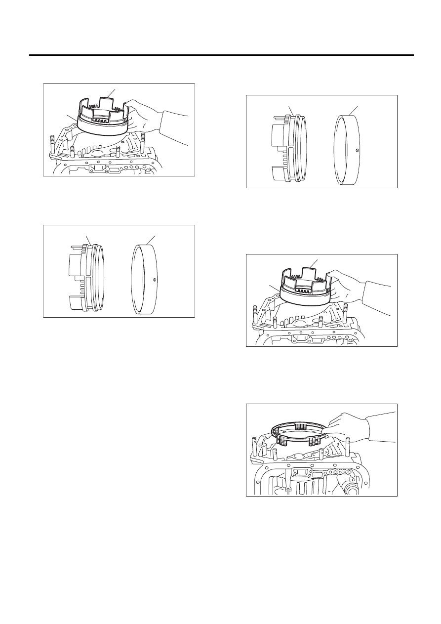
B: INSTALLATION
1) Install 2-4 brake piston to 2-4 brake piston re-
tainer.
2) Install the 2-4 brake piston and 2-4 brake retain-
er by aligning hole of 2-4 brake retainer and hole of
transmission case.
3) Install 2-4 brake piston return spring to transmis-
sion case.
(A) 2-4 brake piston
(B) 2-4 brake piston retainer
(A) 2-4 brake piston
(B) 2-4 brake piston retainer
AT-00287
( A )
( B )
AT-00288
( A )
( B )
(A) 2-4 brake piston
(B) 2-4 brake piston retainer
(A) 2-4 brake piston
(B) 2-4 brake piston retainer
AT-00288
( A )
( B )
AT-00287
( A )
( B )
AT-00286
AT-147
AUTOMATIC TRANSMISSION
2-4 BRAKE
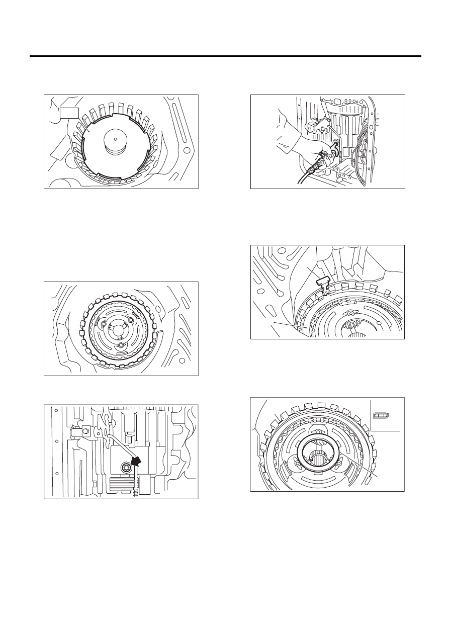
4) Position snap ring in transmission. Using ST,
press the snap ring into place.
ST
498677100
COMPRESSOR
5) Install planetary gear and low clutch assembly to
transmission case.
Install carefully while rotating the low clutch and
planetary gear assembly slowly paying special at-
tention not to damage the seal ring. <Ref. to AT-
137, INSTALLATION, Planetary Gear and Low
Clutch.>
6) Install pressure plate, drive plate, driven plate,
retaining plate and snap ring.
7) Install a new 2-4 brake oil seal to transmission
case.
8) After all 2-4 brake component parts have been
installed, blow in air intermittently and confirm the
operation of the brake.
9) Check the clearance between the retaining plate
and the snap ring.<Ref. to AT-149, INSPECTION,
2-4 Brake.>
10) Be careful not to mistake the location of the leaf
spring to be inserted.
11) Install thrust needle bearing in the correct di-
rection.
12) Install front sun gear.
AT-00289
ST
AT-00254
AT-00284
(A) Leaf spring
(B) Retaining plate
(A) Snap ring
(B) Thrust needle bearing
(C) Upside
(D) Downside
AT-00290
AT-00252
( A )
( B )
AT-00256
( A )
( B )
( C )
( D )
( E )
AT-148
AUTOMATIC TRANSMISSION
2-4 BRAKE
13) Install thrust needle bearing in the correct di-
rection.
14) Install the high clutch assembly. <Ref. to AT-
131, INSTALLATION, High Clutch and Reverse
Clutch.>
15) Install oil pump housing to transmission case.
<Ref. to AT-113, INSTALLATION, Oil Pump.>
16) Install the control valve body and oil pan. <Ref.
to AT-61, INSTALLATION, Control Valve Body.>
17) Install the torque converter clutch case assem-
bly to the transmission case assembly. <Ref. to AT-
110, INSTALLATION, Torque Converter Clutch
Case.>
18) Install the reduction driven gear. <Ref. to AT-
102, INSTALLATION, Reduction Driven Gear.>
19) Install the reduction drive gear. (MPT model)
<Ref. to AT-104, INSTALLATION, Reduction Drive
Gear.>
20) Install the center differential carrier. (VTD mod-
el) <Ref. to AT-106, INSTALLATION, Center Differ-
ential Carrier.>
21) Insert inhibitor switch and transmission con-
nector into stay.
22) Install air breather hose. <Ref. to AT-83, IN-
STALLATION, Air Breather Hose.>
23) Install the oil cooler pipes. <Ref. to AT-80, IN-
STALLATION, ATF Cooler Pipe and Hose.>
24) Install the oil charger pipe with O-ring. <Ref. to
AT-84, INSTALLATION, Oil Charger Pipe.>
25) Insert the input shaft while turning lightly by
hand.
Normal protrusion A:
50 — 55 mm (1.97 — 2.17 in)
26) Install the torque converter clutch assembly.
<Ref. to AT-85, INSTALLATION, Torque Converter
Clutch Assembly.>
27) Install the transmission assembly to the vehi-
cle. <Ref. to AT-42, INSTALLATION, Automatic
Transmission Assembly.>
(A) Hight clutch hub
(B) Thrust needle bearing
(C) Upside
(D) Downside
(E) Outside
AT-00234
( A )
( B )
( E )
( C )
( D )
AT-00291
A
AT-149
AUTOMATIC TRANSMISSION
2-4 BRAKE
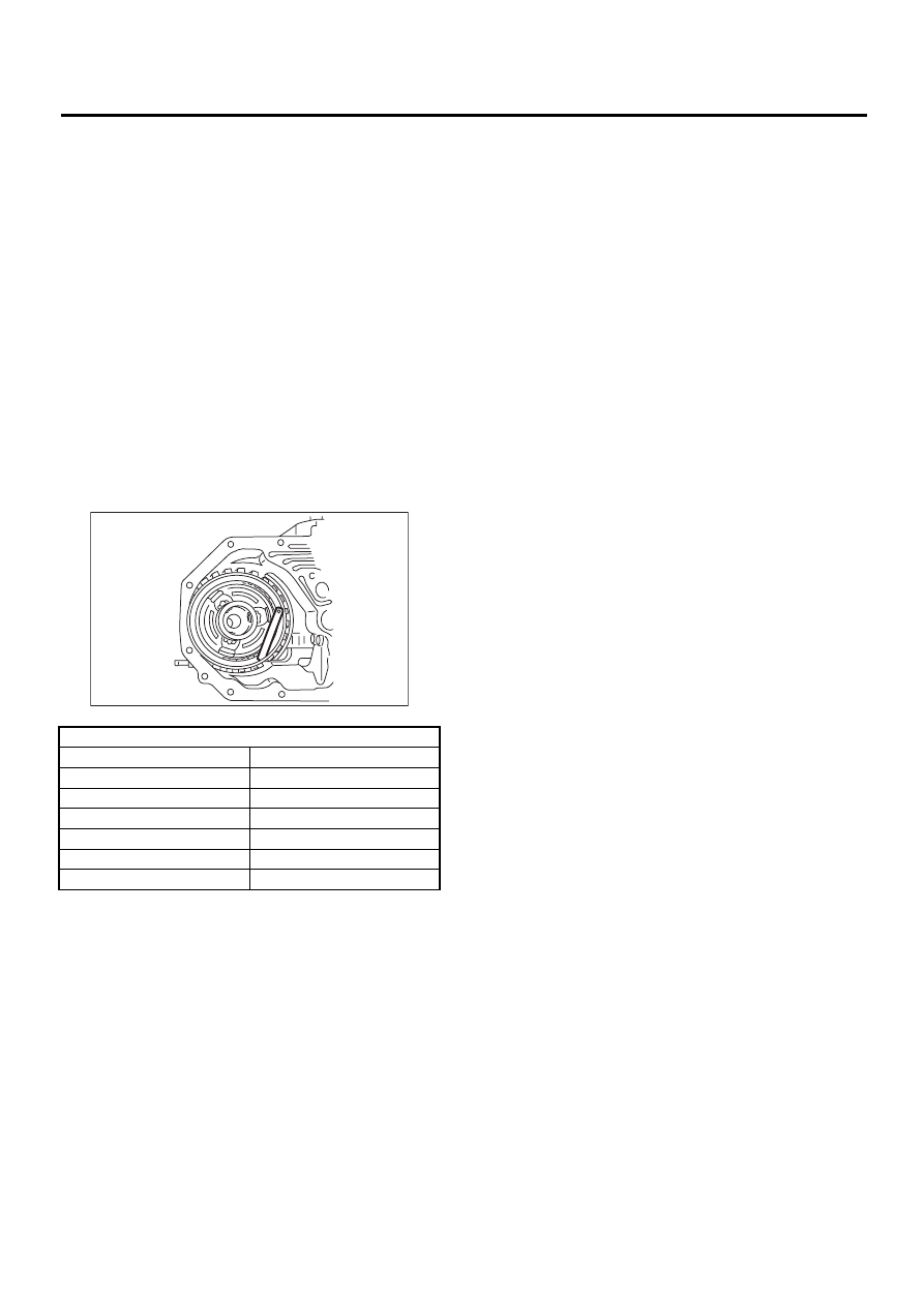
C: INSPECTION
• Drive plate facing for wear and damage
• Snap ring for wear and spring retainer for defor-
mation
• Lip seal and D-ring for damage
• Measure the total end play and adjust to within
specifications.<Ref. to AT-117, ADJUSTMENT, Oil
Pump.>
1) Inspect the clearance between the retaining
plate and the snap ring.
NOTE:
Select a retaining plate with a suitable value from
the following table, so that the clearance becomes
the standard value.
Standard value:
0.8 — 1.2 mm (0.031 — 0.047 in)
Allowable limit:
1.5 mm (0.059 in)
Available retaining plates
Part No.
Thickness mm (in)
31567AA612
5.6 (0.220)
31567AA622
5.8 (0.228)
31567AA632
6.0 (0.236)
31567AA642
6.2 (0.244)
31567AA652
6.4 (0.252)
31567AA662
6.6 (0.260)
AT-00292
Нет комментариевНе стесняйтесь поделиться с нами вашим ценным мнением.
Текст