Subaru Legacy III (2000-2003 year). Service manual — part 897
AB-14
AIRBAG SYSTEM (DIAGNOSTICS)
GENERAL DESCRIPTION
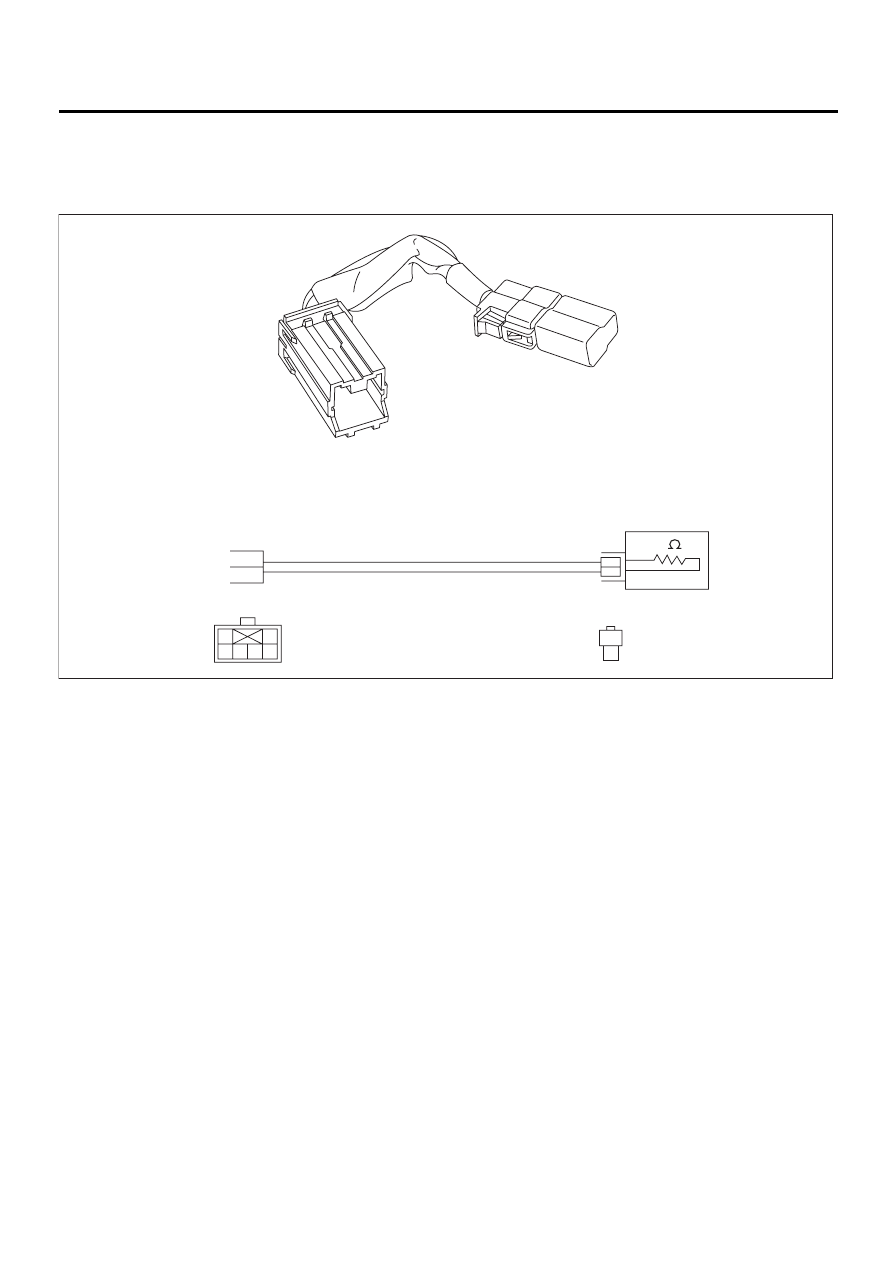
6. AIRBAG RESISTOR
The airbag resistor is used during diagnostics. The airbag resistor has the same resistance as the airbag
module and thus provides safety when used instead of the airbag module. It also makes it possible to finish,
diagnostics in less time.
AB-00067
PN 98299PA040
3
Y
R
4
1
2
3
6 5 4
Y
R
2
1
3
1
2
AB-15
AIRBAG SYSTEM (DIAGNOSTICS)
ELECTRICAL COMPONENTS LOCATION
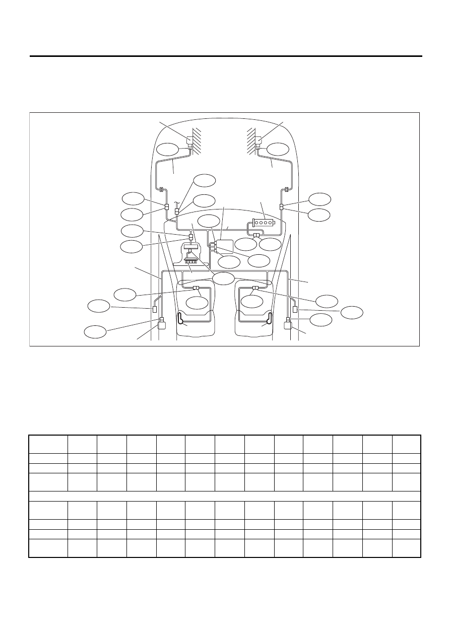
4. Electrical Components Location
A: LOCATION
1. LHD MODEL
(1) Front sub sensor (LH)
(7) Roll connector
(13) Side airbag sensor (RH)
(2) Front sub sensor (RH)
(8) Airbag main harness
(14) Side airbag inflator (LH)
(3) Front sub sensor harness (LH)
(9) Inflator (Driver)
(15) Side airbag inflator (RH)
(4) Front sub sensor harness (RH)
(10) Side airbag harness (LH)
(a) To body harness
(5) Airbag control module with safety
sensor and electric sensor
(11) Side airbag harness (RH)
(b) To seal belt pretensioner (LH)
(12) Side airbag sensor (LH)
(c) To seal belt pretensioner (RH)
(6) Inflator (Passenger)
Connec-
tor No.
(AB1)
(AB2)
(AB3)
(AB6)
(AB7)
(AB8)
(AB9)
(AB10)
(AB11)
(AB12)
(AB13)
(AB14)
Pole
12
2
2
28
2
2
2
2
2
2
2
2
Color
Yellow
Yellow
Yellow
Yellow
Black
Yellow
Yellow
Yellow
Blue
Blue
Yellow
Blue
Male/
Female
Male
Male
Male
Female
Female
Female
Female
Male
Male
Female
Female
Male
Connec-
tor No.
(AB15)
(AB16)
(AB17)
(AB18)
(AB19)
(AB20)
(AB21)
(AB23)
(AB24)
(AB25)
(AB26)
(AB28)
Pole
2
2
12
12
2
2
2
4
2
2
2
4
Color
Blue
Yellow
Yellow
Yellow
Yellow
Yellow
Yellow
Yellow
Yellow
Yellow
Yellow
Yellow
Male/
Female
Female
Female
Female
Female
Female
Male
Female
Female
Female
Male
Female
Female
AB16
AB8
AB3
AB18
AB6
( 1 )
( 2 )
( 4 )
( 6 )
(14)
( a )
AB15
AB14
AB13
( 3 )
AB12
AB11
B31
AB1
( 8 )
( 7 )
AB17
( 9 )
(15)
(13)
(11)
AB26
( c )
AB28
AB25
AB24
AB20
AB19
AB9
AB10
( 5 )
(12)
(10)
AB21
( b )
AB23
AB7
AB-00347
AB-16
AIRBAG SYSTEM (DIAGNOSTICS)
ELECTRICAL COMPONENTS LOCATION
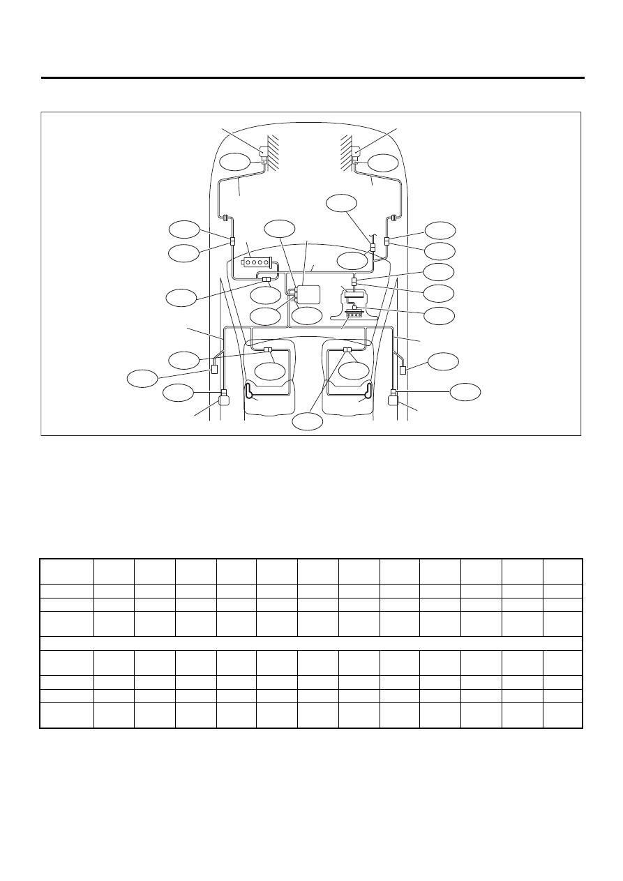
2. RHD MODEL
(1) Front sub sensor (LH)
(7) Roll connector
(13) Side airbag sensor (RH)
(2) Front sub sensor (RH)
(8) Airbag main harness
(14) Side airbag inflator (LH)
(3) Front sub sensor harness (LH)
(9) Inflator (Driver)
(15) Side airbag inflator (RH)
(4) Front sub sensor harness (RH)
(10) Side airbag harness (LH)
(a) To body harness
(5) Airbag control module with safety
sensor and electric sensor
(11) Side airbag harness (RH)
(b) To seal belt pretensioner (LH)
(12) Side airbag sensor (LH)
(c) To seal belt pretensioner (RH)
(6) Inflator (Passenger)
Connec-
tor No.
(AB1)
(AB2)
(AB3)
(AB6)
(AB7)
(AB8)
(AB9)
(AB10)
(AB11)
(AB12)
(AB13)
(AB14)
Pole
12
2
2
28
2
2
2
2
2
2
2
2
Color
Yellow
Yellow
Yellow
Yellow
Black
Yellow
Yellow
Yellow
Blue
Blue
Yellow
Blue
Male/
Female
Male
Male
Male
Female
Female
Female
Female
Male
Male
Female
Female
Male
Connec-
tor No.
(AB15)
(AB16)
(AB17)
(AB18)
(AB19)
(AB20)
(AB21)
(AB23)
(AB24)
(AB25)
(AB26)
(AB28)
Pole
2
2
12
12
2
2
2
4
2
2
2
4
Color
Blue
Yellow
Yellow
Yellow
Yellow
Yellow
Yellow
Yellow
Yellow
Yellow
Yellow
Yellow
Male/
Female
Female
Female
Female
Female
Female
Male
Female
Female
Female
Male
Female
Female
AB-00348
AB25
AB24
AB20
AB19
AB9
AB10
AB18
B31
AB16
AB13
AB15
AB14
AB8
AB3
AB26
AB28
AB7
AB17
AB6
AB23
AB21
AB12
AB11
AB1
( 2 )
( 3 )
( 4 )
( 5 )
( 6 )
( 7 )
( 8 )
( 9 )
(10)
(11)
(12)
(13)
(14)
(15)
( a )
( b )
( c )
( 1 )
AB-17
AIRBAG SYSTEM (DIAGNOSTICS)
AIRBAG CONNECTOR
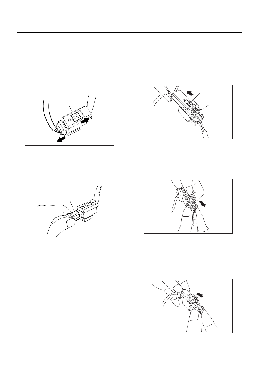
5. Airbag Connector
A: OPERATION
1. POWER SUPPLY
1) How to disconnect:
(1) Move the slide lock (A) in the direction of the
arrow.
(2) Pull the female connector in the direction of
the arrow with slide lock (A) moved.
CAUTION:
When pulling, be sure to hold onto the conector
and not the wire.
2) How to connect:
Holding the connector (A), and push it in carefully
until a connecting sound is head.
CAUTION:
Be sure to insert the connector in until it locks.
Then pull on it gently to make sure that it is
locked.
2. DRIVER'S AIRBAG, PASSENGER’S AIR-
BAG, SIDE AIRBAG, FRONT SUB SENSOR
HARNESS TO AIRBAG MAIN HARNESS
AND PRETENSIONER
1) How to disconnect:
(1) Push lock arm (A).
(2) With lock arm (A) pushed in, move slide lock
(B) in the direction of the arrow.
(3) With slide lock (B) pulled, remove lock arm
(A) to its original position, and then pull in the di-
rection of the arrow and separate the connector.
CAUTION:
When pulling, be sure to hold onto the connec-
tor and not the wire.
2) How to connect:
Holding the connector, and push it in carefully until
a connecting sound is heard.
CAUTION:
Be sure to insert the connector in until it locks.
Then pull on it gently to make sure that it is
locked.
AB-00015
( A )
AB-00016
( A )
AB-00017
( A )
( B )
AB-00018
AB-00019
Нет комментариевНе стесняйтесь поделиться с нами вашим ценным мнением.
Текст