Subaru Legacy III (2000-2003 year). Service manual — part 207
EN(H4SOw/oOBD)-18
ENGINE (DIAGNOSTICS)
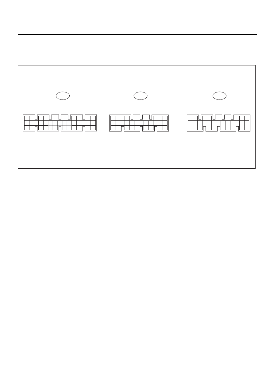
ENGINE CONTROL MODULE (ECM) I/O SIGNAL
5. Engine Control Module (ECM)
I/O Signal
A: ELECTRICAL SPECIFICATION
To:
17
30
14
28
16
18
31
15
29
8
23
35
22
34
7
8
23
20
22
11
21
12
10
2
3
1
9
17
14
28
19
16
13
27
18
15
26 25 24
6
4
7
5
8
23
22
11
21
12
10
24
2
3
1
9
B134
To:
B135
20
33
19
32
6 5
21
13
27
11
12
26
10
25 24
4
2
3
1
9
To:
B136
20
17
14
28
29
30
19
16
13
27
18
15
26
25
6
4
7
5
EN-01038

EN(H4SOw/oOBD)-19
ENGINE (DIAGNOSTICS)
ENGINE CONTROL MODULE (ECM) I/O SIGNAL
*: With immobilizer
Content
Connec-
tor No.
Terminal
No.
Signal (V)
Note
Ignition SW
Engine ON
(Idling)
ON (Engine OFF)
Crankshaft
position
sensor
Signal (+)
B135
*2
1
0
±
6
Sensor output waveform
Signal (
−
)
B135
8
0
0
—
Shield
B135
10
0
0
—
Camshaft
position
sensor
Signal (+)
B135
*1
2
0
±
6
Sensor output waveform
Signal (
−
)
B135
8
0
0
—
Shield
B135
10
0
0
—
Intake air
tempera-
ture sensor
Signal
B136
13
2.3 — 2.5
1.4 — 1.6
Ambient temperature: 25
°
C (77
°
F)
Throttle
position
sensor
Signal
B136
17
Fully closed: 0.5
±
0.3
Fully opened: 4.3
±
0.3
—
Power
supply
B136
15
5
5
—
GND
B136
16
0
0
—
Oxygen
sensor
Signal
B136
7
0
Rich mixture: 0.7
Lean mixture: 0
Shield
B136
23
0
0
—
Engine cool-
ant temper-
ature sensor
Signal
B136
14
0.6 — 1.0
0.6 — 1.0
After warm-up
GND
B136
16
0
0
—
Vehicle speed sensor
B135
24
0 or 5
0 or 5
“5” and “0” are repeatedly displayed
when vehicle is driven.
Starter switch
B135
28
0
0
Cranking: 10 to 14
A/C switch
B135
27
ON: 10 — 13
OFF: 0
ON: 13 — 14
OFF: 0
—
Ignition switch
B135
7
10 — 13
13 — 14
—
Neutral position switch
(MT)
B135
26
ON: 5
OFF: 0
Switch is ON when gear is in neutral
position.
Park/Neutral position
switch (AT)
B135
26
ON: 0
OFF: 5
Switch is ON when shift lever is in
“P” or “N” position.
Test mode connector
B135
14
5
5
When connected: 0
Read memory connector
B135
15
5
5
When connected: 0
Back-up power supply
B136
9
10 — 13
13 — 14
—
Control unit power sup-
ply
B136
1
10 — 13
13 — 14
—
2
Ignition con-
trol
# 1, # 2
B134
25
0
3.4, max.
—
# 3, # 4
B134
26
0
3.4, max.
—
Fuel injector
# 1
B134
4
10 — 13
13 — 14
Waveform
# 2
B134
13
10 — 13
13 — 14
Waveform
# 3
B134
14
10 — 13
13 — 14
Waveform
# 4
B134
15
10 — 13
13 — 14
Waveform

EN(H4SOw/oOBD)-20
ENGINE (DIAGNOSTICS)
ENGINE CONTROL MODULE (ECM) I/O SIGNAL
*: With immobilizer
Content
Connec-
tor No.
Terminal
No.
Signal (V)
Note
Ignition SW
Engine ON (Idling)
ON (Engine OFF)
Idle air con-
trol sole-
noid valve
Signal 1
B134
5
—
1 — 13
Waveform
Signal 2
B134
6
—
1 — 13
Waveform
Signal 3
B134
19
—
1 — 13
Waveform
Signal 4
B134
20
—
1 — 13
Waveform
Torque control signal 1
B135
16
5
5
—
Torque control signal 2
B135
17
5
5
—
Fuel pump relay control
B134
29*
16
ON: 0
OFF: 10 — 13
0
—
A/C relay control
B134
17
ON: 0
OFF: 10 — 13
ON: 0
OFF: 13 — 14
—
Radiator fan relay 1 con-
trol
B134
3
ON: 0
OFF: 10 — 13
ON: 0
OFF: 13 — 14
—
Radiator fan relay 2 con-
trol
B134
12
ON: 0
OFF: 10 — 13
ON: 0
OFF: 13 — 14
—
Self-shutoff control
B135
19
10 — 13
13 — 14
—
Malfunction indicator
lamp
B134
11
—
—
Light “ON”: 1, max.
Light “OFF”: 10 — 14
Engine speed output
B134
30
—
0 — 13, min.
Waveform
Knock sen-
sor
Signal
B136
4
2.8
2.8
—
Shield
B136
25
0
0
—
Pressure
sensor
Signal
B136
5
3.4 — 3.6
1.2 — 1.8
—
Power
supply
15
5
5
—
GND
16
0
0
—
Purge control solenoid
valve
B134
2
ON: 0
OFF: 10 — 13
ON: 0
OFF: 13 — 14
—
GND (sensors)
B136
16
0
0
—
GND (injectors)
B134
7
0
0
—
GND (ignition system)
B134
27
0
0
—
GND (power supply)
B134
8
0
0
—
GND (control systems)
B136
21
0
0
—
B136
22
0
0
—
Select monitor signal
B135
11
—
—
—
12
—
—
—
Power steering switch
B135
13
ON: 0
OFF: 10 — 13
ON: 0
OFF: 10 — 13
—
Torque control cut signal
B134
31
8
8
—
AT load signal
B136
11
0 — 0.3
0.8 — 1.2
—
MT/AT identification
B135
25
MT: 0
AT: 5
MT: 0
AT: 5
—
EN(H4SOw/oOBD)-21
ENGINE (DIAGNOSTICS)
SUBARU SELECT MONITOR
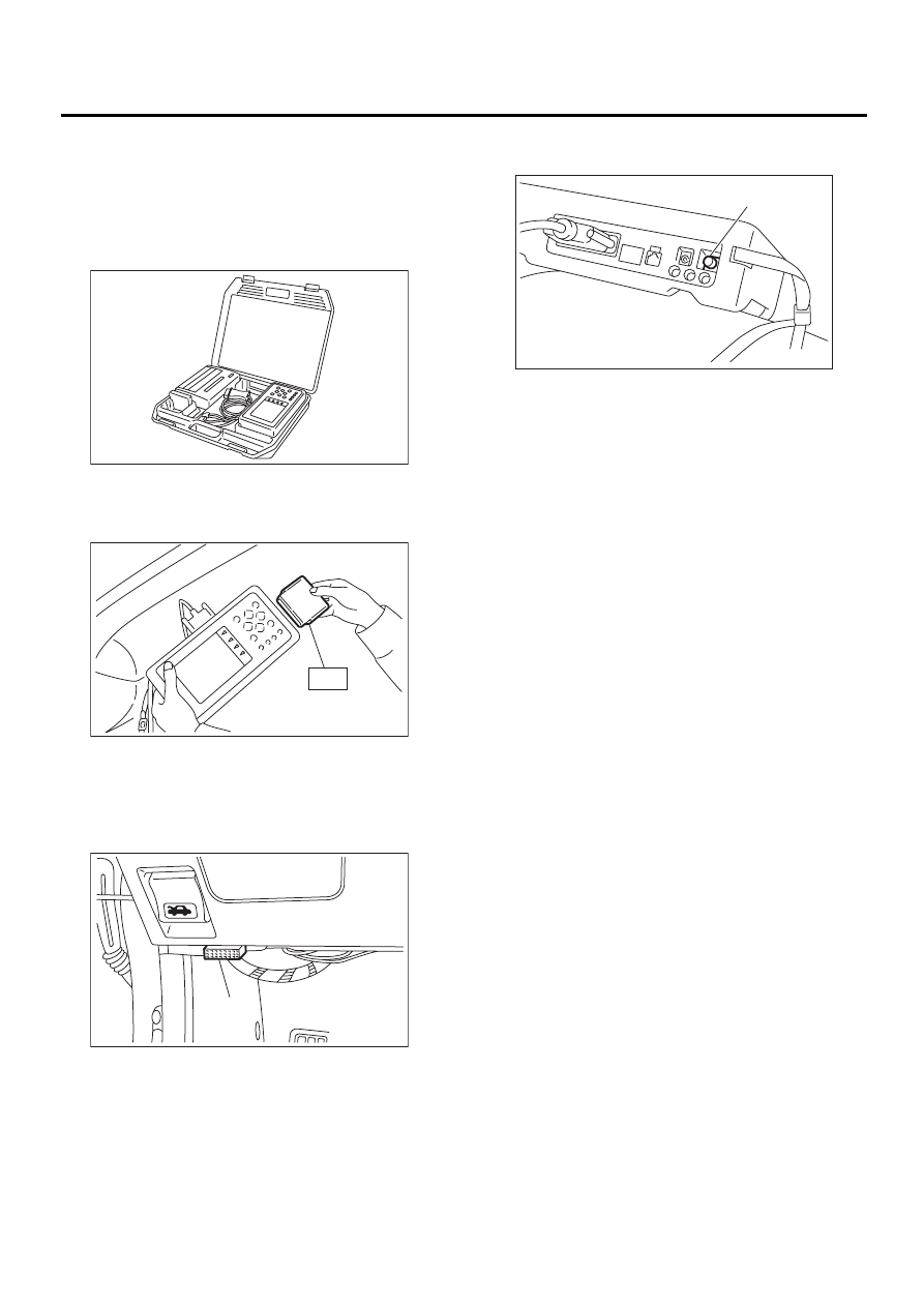
6. Subaru Select Monitor
A: OPERATION
1. HOW TO USE SUBARU SELECT MONI-
TOR
1) Prepare Subaru Select Monitor kit.
2) Connect diagnosis cable to Subaru Select Mon-
itor.
3) Insert cartridge into Subaru Select Monitor.
4) Connect Subaru Select Monitor to data link con-
nector.
(1) Data link connector (A) located in the lower
portion of the instrument panel (on the driver's
side).
(2) Connect diagnosis cable to data link con-
nector.
CAUTION:
Do not connect scan tools except for Subaru
Select Monitor.
5) Turn ignition switch to ON (engine OFF) and
Subaru Select Monitor switch to ON.
6) Using Subaru Select Monitor, call up diagnostic
trouble code(s) and various data, then record them.
2. READ DIAGNOSTIC TROUBLE CODE
(DTC) FOR ENGINE.
Refer to Read Diagnostic Trouble Code for infor-
mation about how to indicate DTC. <Ref. to
EN(H4SOw/oOBD)-24, Read Diagnostic Trouble
Code (DTC).>
3. READ CURRENT DATA SHOWN ON DIS-
PLAY.
1) On the «Main Menu» display screen, select the
{2. Each System Check} and press the [YES] key.
2) On the «System Selection Menu» display
screen, select the {Engine Control System} and
press the [YES] key.
3) Press the [YES] key after displayed the informa-
tion of engine type.
4) On the «Engine Diagnosis» display screen, se-
lect the {1. Current Data Display & Save} and press
the [YES] key.
5) On the «Data Display Menu» display screen, se-
lect the {1. 12 Data Display} and press the [YES]
key.
6) Using the scroll key, move the display screen up
or down until the desired data is shown.
EN-00038
ST
EN-00039
EN-00710
( A )
(A) Power switch
EN-00040
( A )
Нет комментариевНе стесняйтесь поделиться с нами вашим ценным мнением.
Текст