Subaru Legacy III (2000-2003 year). Service manual — part 327

EN(H6DO)-110
ENGINE (DIAGNOSTICS)
DIAGNOSTIC PROCEDURE WITH DIAGNOSTIC TROUBLE CODE (DTC)
6
CHECK POWER SUPPLY TO REAR OXY-
GEN SENSOR.
1) Turn ignition switch to OFF.
2) Disconnect connector from rear oxygen
sensor.
3) Turn ignition switch to ON.
4) Measure voltage between rear oxygen sen-
sor connector and engine ground or chas-
sis ground.
Connector & terminal
(T6) No. 2 (+) — Chassis ground (
−−−−
):
Does the measured value exceed the spec-
ified value?
10 V
Repair power sup-
ply line.
NOTE:
In this case, repair
the following:
• Open circuit in
harness between
main relay and
rear oxygen sen-
sor connector
• Poor contact in
rear oxygen sen-
sor connector
• Poor contact in
coupling connector
7
CHECK REAR OXYGEN SENSOR.
1) Turn ignition switch to OFF.
2) Measure resistance between rear oxygen
sensor connector terminals.
Terminals
No. 1 — No. 2:
Is the measured value less than the speci-
fied value?
30
Ω
Repair harness
and connector.
NOTE:
In this case, repair
the following:
• Open circuit in
harness between
rear oxygen sen-
sor and ECM con-
nector
• Poor contact in
rear oxygen sen-
sor connector
• Poor contact in
ECM connector
• Poor contact in
coupling connector
Replace rear oxy-
gen sensor. <Ref.
to FU(H6DO)-45,
Rear Oxygen Sen-
sor.>
Step
Value
Yes
No
EN(H6DO)-111
ENGINE (DIAGNOSTICS)
DIAGNOSTIC PROCEDURE WITH DIAGNOSTIC TROUBLE CODE (DTC)
MEMO:
EN(H6DO)-112
ENGINE (DIAGNOSTICS)
DIAGNOSTIC PROCEDURE WITH DIAGNOSTIC TROUBLE CODE (DTC)
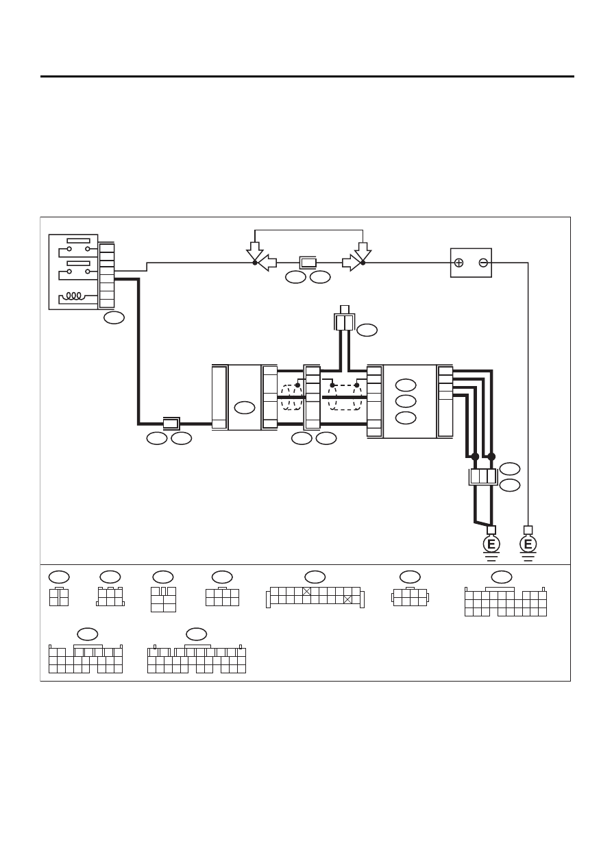
E: DTC P0038 — HO2S HEATER CONTROL CIRCUIT HIGH (BANK 1 SENSOR
2) —
• DTC DETECTING CONDITION:
• Two consecutive driving cycles with fault
CAUTION:
After repair or replacement of faulty parts, conduct Clear Memory Mode <Ref. to EN(H6DO)-54, OP-
ERATION, Clear Memory Mode.> and Inspection Mode <Ref. to EN(H6DO)-47, OPERATION, Inspec-
tion Mode.>.
• WIRING DIAGRAM:
EN-01088
BATTERY
F44
B61
6
T5
B19
B47
MAIN RELAY
2
1
3
5
4
6
F44
1 2 3 4
5 6 7 8
C13
B17
B19
B26
D21
D31
D9
D8
REAR
OXYGEN
SENSOR
5
3
6
4
1
3
4
2
1
5
B252
B83
B19
T5
T6
E49
B47
T6
B136
C:
D:
B135
B:
3
4
5
6
1
2
5
7
ECM
B135
B:
B136
C:
B137
D:
3
4
1
2
1 2
7
8 9
5
6
3
4
10 11 12
19 20 21
13 14 15 16
17 18
22 23 24
5 6
7 8
2
1
9
4
3
10
24
22
23
25
11 12 13 14 15
26 27 28
16 17 18 19
20 21
B137
1
2
7
8
9
5
6
3
4
10 11 12
19 20 21
29 30 31
13 14 15 16 17
27 28
18
22 23 24 25 26
RHD
LHD
LHD
RHD
B252
1 2 3 4
5 6 7 8
B19
4
1 2 3
6
5
2
B83
1 2 3 4
5 6 7 8 9 10
11 12
19
20
13 14 15 16 17 18

EN(H6DO)-113
ENGINE (DIAGNOSTICS)
DIAGNOSTIC PROCEDURE WITH DIAGNOSTIC TROUBLE CODE (DTC)
Step
Value
Yes
No
1
CHECK OUTPUT SIGNAL FROM ECM.
Measure voltage between ECM connector and
chassis ground.
Connector & terminal
(B136) No. 13 (+) — Chassis ground (
−−−−
):
Does the measured value exceed the specified
value?
8 V
2
CHECK CURRENT DATA.
1) Repair battery short circuit in harness
between ECM and rear oxygen sensor con-
nector.
2) Turn ignition switch to ON.
3) Read data of rear oxygen sensor heater
current using Subaru Select Monitor or the
OBD-II general scan tool.
Does the measured value exceed the spec-
ified value?
NOTE:
• Subaru Select Monitor
For detailed operation procedure, refer to the
“READ CURRENT DATA FOR ENGINE”.
<Ref. to EN(H6DO)-34, Subaru Select Moni-
tor.>
• OBD-II general scan tool
For detailed operation procedure, refer to the
OBD-II General Scan Tool Instruction Manual.
7 A
Replace ECM.
<Ref. to
FU(H6DO)-46,
Engine Control
Module.>
END
3
CHECK POOR CONTACT.
Check poor contact in ECM connector.
Is there poor contact in ECM connector?
There is poor contact.
Repair poor con-
tact in ECM con-
nector.
END
Нет комментариевНе стесняйтесь поделиться с нами вашим ценным мнением.
Текст