Subaru Legacy III (2000-2003 year). Service manual — part 298
SC(H6DO)-16
STARTING/CHARGING SYSTEMS
GENERATOR
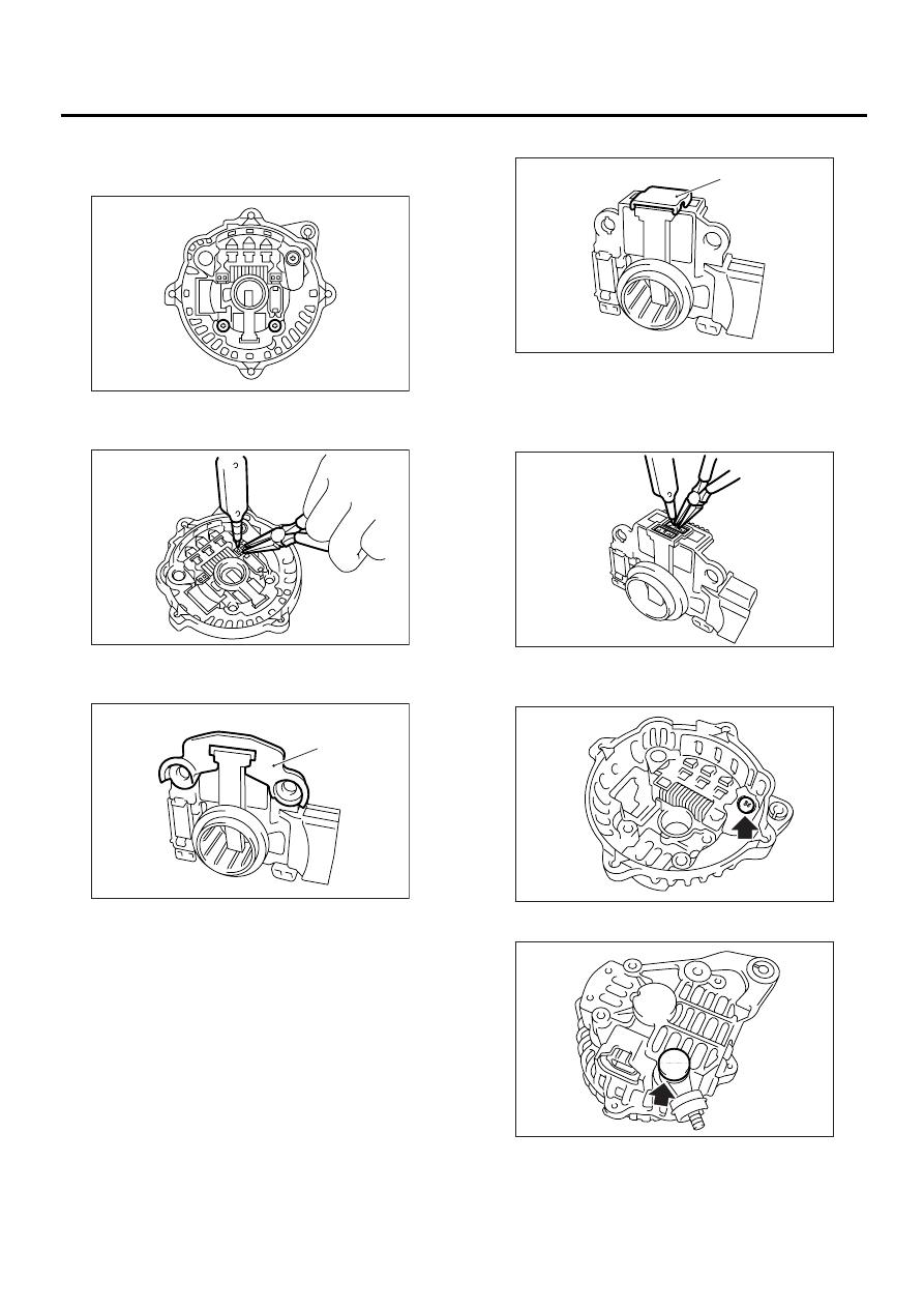
8) Remove the IC regulator as follows.
(1) Remove the screws which secure IC regula-
tor to rear cover.
(2) Unsolder the connection between IC regula-
tor and rectifier to remove the IC regulator.
9) Remove the brush as follows.
(1) Remove cover A.
(2) Remove the cover B.
(3) Separate the brush from connection to re-
move.
10) Remove the rectifier as follows.
(1) Remove the bolts which secure the rectifier.
(2) Remove the cover of terminal B.
(A) Cover A
SC-00084
SC-00085
SC-00086
(A)
(A) Cover B
SC-00087
(A)
SC-00088
SC-00089
SC-00090
SC(H6DO)-17
STARTING/CHARGING SYSTEMS
GENERATOR
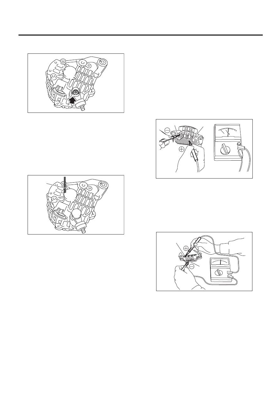
(3) Remove the nut of terminal B, and then re-
move the rectifier.
D: ASSEMBLY
To assemble, reverse order of disassembly.
1) Pulling up brush
Before assembling, press the brush down into
brush holder, and then fix them in that position by
passing a [1 mm (0.08 in) dia. length 4 to 5 cm (1.6
to 2.0 in)] wire through the hole shown in the figure.
CAUTION:
Be sure to remove the wire after reassembly.
2) Install the ball bearing.
(1) Set the ball bearing on the front cover, and
then securely install an appropriate tool (such as
a fit socket wrench) to the bearing outer race.
(2) Press the ball bearing into the specified po-
sition using a press.
(3) Install the bearing retainer.
3) Press the bearing (rear side) into the rotor shaft
using a press to install.
4) Heat the bearing box in rear cover [50 to 60
°
C
(122 to 140
°
F)], and then press the rear bearing
into rear cover.
CAUTION:
Grease should not be applied to rear bearing.
Remove the oil completely if it is found on bear-
ing box.
5) After reassembly, turn the pulley by hand to
check that rotor turns smoothly.
E: INSPECTION
1. DIODE
CAUTION:
Never use a mega tester (measuring use for
high voltage) or any other similar measure for
this test; otherwise, the diodes may be dam-
aged.
1) Checking positive diode
Check for continuity between the diode lead and
positive side heat sink. The positive diode is in
good condition if resistance is 1
Ω
or less only in the
direction from the diode lead to heat sink.
2) Checking negative diode
Check for continuity between the negative side
heat sink and diode lead. The negative diode is in
good condition if resistance is 1
Ω
or less only in the
direction from the heat sink to diode lead.
(A) Wire
SC-00091
SC-00092
(A)
(A) Diode lead
(B) Heat sink (Positive side)
(A) Diode lead
(B) Heat sink (Negative side)
( A )
( B )
SC-00042
SC-00043
( A )
( B )
SC(H6DO)-18
STARTING/CHARGING SYSTEMS
GENERATOR
2. ROTOR
1) Slip ring surface
Inspect the slip rings for contamination or any
roughness of the sliding surface. Repair the slip
ring surface using a lathe or sand paper.
2) Slip ring outer diameter
Measure the slip ring outer diameter. If the slip ring
is worn replace rotor assembly.
Slip ring outer diameter:
Standard
22.7 mm (0.894 in)
Limit
22.1 mm (0.870 in)
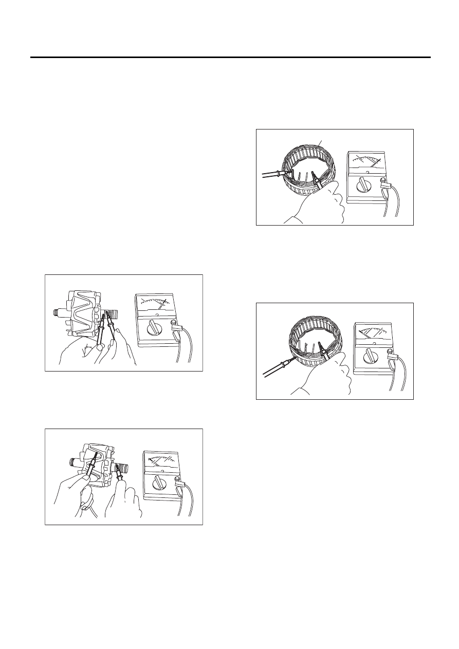
3) Continuity test
Check the resistance between slip rings using cir-
cuit tester.
If the resistance is not within specification, replace
the rotor assembly.
Specified resistance:
Approx. 2.0 — 2.4
Ω
Ω
Ω
Ω
4) Insulation test
Check the continuity between slip ring and rotor
core or shaft. If resistance is 1
Ω
or less, the rotor
coil is grounded, and so replace the rotor assem-
bly.
5) Ball bearing (rear side)
Check the rear ball bearing. Replace if it is noisy or
if the rotor does not turn smoothly.
3. STATOR
1) Continuity test
Inspect the stator coil for continuity between each
end of the lead wires. If resistance is 1 M
Ω
or
more, the lead wire is broken, and so replace the
stator assembly.
2) Insulation test
Inspect the stator coil for continuity between stator
core and each end of lead wire. If resistance is 1
Ω
or less, the stator coil is grounded, and so replace
the stator assembly.
SC-00044
SC-00045
(A) Stator
( A )
SC-00047
SC-00048
SC(H6DO)-19
STARTING/CHARGING SYSTEMS
GENERATOR
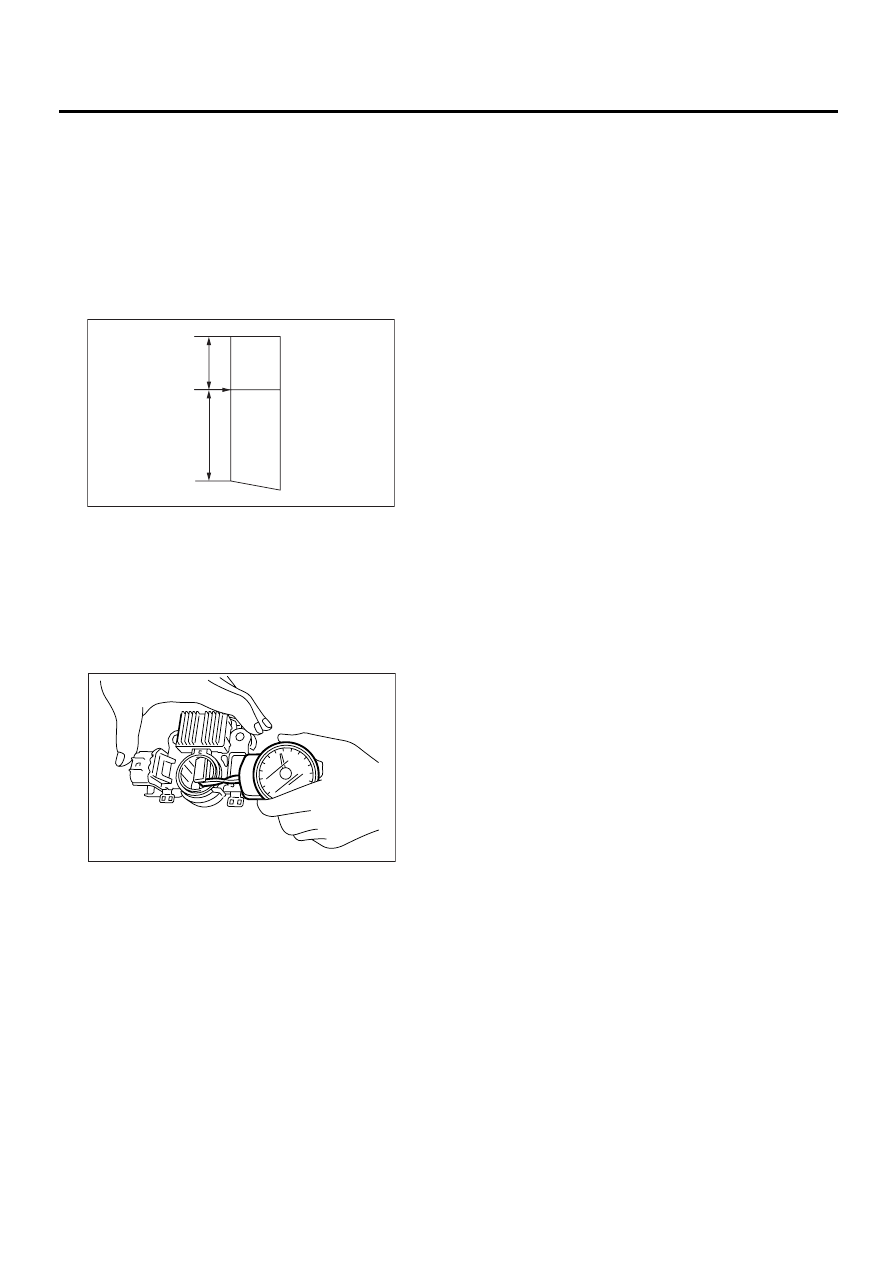
4. BRUSH
1) Measure the length of each brush. If wear ex-
ceeds the service limit, replace the brush. Each
brush has the service limit mark (A) on it.
Brush length:
Standard
18.5 mm (0.728 in)
Service limit
5.0 mm (0.197 in)
2) Checking brush spring for proper pressure
Using a spring pressure indicator, push the brush
into the brush holder until its tip protrudes 2 mm
(0.08 in). Then measure the pressure of brush
spring. If the pressure is less than 2.2 N (224 g,
7.91 oz), replace the brush spring with a new one.
The new spring must have a pressure of 4.8 to 6.0
N (489 to 612 g, 17.26 to 21.60 oz).
5. BEARING (FRONT SIDE)
Check the front ball bearing. If the resistance is felt
while rotating, or if abnormal noise is heard, re-
place the ball bearing.
18.5
(0.728)
(0.197)
5.0
SC-00162
( A )
SC-00093
Нет комментариевНе стесняйтесь поделиться с нами вашим ценным мнением.
Текст