Subaru Legacy III (2000-2003 year). Service manual — part 570
AT-14
AUTOMATIC TRANSMISSION (DIAGNOSTICS)
TRANSMISSION CONTROL MODULE (TCM) I/O SIGNAL
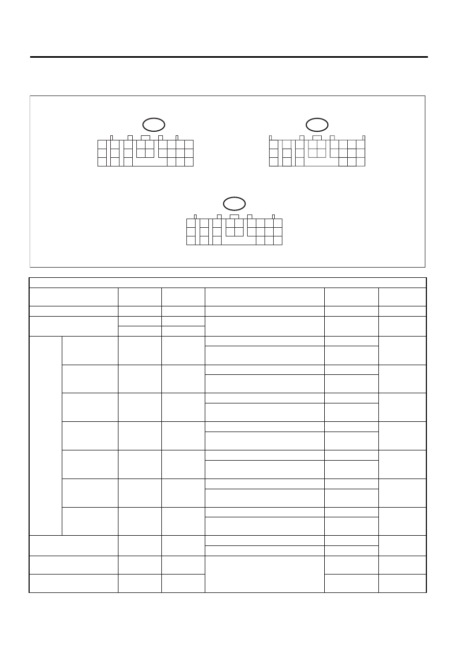
5. Transmission Control Module (TCM) I/O Signal
A: ELECTRICAL SPECIFICATION
Check with ignition switch ON.
Content
Connector
No.
Terminal
No.
Measuring conditions
Voltage (V)
Resistance to
body (ohms)
Back-up power supply
B56
1
Ignition switch OFF
10 — 13
—
Ignition power supply
B54
23
Ignition switch ON (with engine OFF)
10 — 13
—
B54
24
Inhibitor
switch
“P” range switch
B55
1
Select lever in “P” range
Less than 1
—
Select lever in any other than “P”
range (except “N” range)
More than 8
“N” range switch
B55
14
Select lever in “N” range
Less than 1
—
Select lever in any other than “N”
range (except “P” range)
More than 8
“R” range switch
B55
3
Select lever in “R” range
Less than 1
—
Select lever in any other than “R”
range
More than 8
“D” range switch
B55
4
Select lever in “D” range
Less than 1
—
Select lever in any other than “D”
range
More than 8
“3” range switch
B55
5
Select lever in “3” range
Less than 1
—
Select lever in any other than “3”
range
More than 8
“2” range switch
B55
6
Select lever in “2” range
Less than 1
—
Select lever in any other than “2”
range
More than 8
“1” range switch
B55
7
Select lever in “1” range
Less than 1
—
Select lever in any other than “1”
range
More than 8
Brake switch
B55
12
Brake pedal depressed.
More than 10.5
—
Brake pedal released.
Less than 1
VDC communication signal
+
B56
9
Ignition ON
(+) — (–)
Pulse signal
—
VDC communication signal
–
B56
18
(+) — (–)
Pulse signal
—
AT-00642
to
B54
1
2
7
8
9
5
6
3
4
10
11
12
19
20
21
13
14
15
16
17
18
22
23
24
to
B55
1
2
3
4
10
11
12
19
20
21
13
5
6
14
15
7
8
9
16
17
18
22
23
24
to
B56
1
2
7
8
9
5
6
3
4
10
11
12
19
20
21
13
14
15
16
17
18
22
23
24
AT-15
AUTOMATIC TRANSMISSION (DIAGNOSTICS)
TRANSMISSION CONTROL MODULE (TCM) I/O SIGNAL
Kick-down switch
B55
11
Throttle fully opened.
Less than 1
—
Throttle fully closed.
More than 6.5
AT OIL TEMP warning light
B56
10
Light ON
Less than 1
—
Light OFF
More than 9
Throttle position sensor
B54
3
Throttle fully closed.
0.2 — 1.0
—
Throttle fully open.
4.2 — 4.7
Throttle position sensor
power supply
B54
2
Ignition switch ON (With engine OFF)
4.8 — 5.3
—
ATF temperature sensor
B54
11
ATF temperature 20
°
C (68
°
F)
1.6 — 2.0
2.1 k — 2.9 k
ATF temperature 80
°
C (176
°
F)
0.4 — 0.9
275 — 375
Rear vehicle speed sensor
B55
24
Vehicle stopped.
0
450 — 650
Vehicle speed at least 20 km/h (12
MPH)
More than 1
(AC range)
Front vehicle speed sensor
B55
18
Vehicle stopped.
0
450 — 650
Vehicle speed at least 20 km/h (12
MPH)
More than 1
(AC range)
Torque converter turbine
speed sensor
B55
8
Engine idling after warm-up.
(D range)
0
450 — 650
Engine idling after warm-up.
(N range)
More than 1
(AC range)
Vehicle speed output sig-
nal
B56
17
Vehicle speed at most 10 km/h (6
MPH)
Less than 1
←
→
More than 4
—
Engine speed signal
B55
17
Ignition switch ON (with engine OFF)
0
—
Ignition switch ON (with engine ON)
8 — 11
Cruise set signal
B55
22
When cruise control is set (SET lamp
ON)
Less than 1
—
When cruise control is not set (SET
lamp OFF)
More than 6.5
Torque control signal 1
B56
5
Ignition switch ON (with engine ON)
More than 4
—
Torque control signal 2
B56
14
Ignition switch ON (with engine ON)
More than 4
—
Torque control cut signal
B55
10
Ignition switch ON
8
—
Intake manifold pressure
signal
(Non-TURBO model)
B54
1
Engine idling after warm-up.
0.4 — 1.6
—
Shift solenoid 1
B54
22
1st or 4th gear
More than 9
10 — 16
2nd or 3rd gear
Less than 1
Mass air flow signal
(TURBO model)
B54
1
Idling condition after warm-up
0.9 — 1.4
—
Shift solenoid 2
B54
5
1st or 2nd gear
More than 9
10 — 16
3rd or 4th gear
Less than 1
Line pressure duty sole-
noid
B54
9
Ignition switch ON (with engine OFF)
Throttle fully closed after warm-up.
1.5 — 4.0
2.0 — 4.5
Ignition switch ON (with engine OFF)
Throttle fully open after warm-up.
Less than 0.5
Lock-up duty solenoid
B54
7
When lock up occurs.
More than 8.5
10 — 17
When lock up is released.
Less than 0.5
Transfer duty solenoid
(Without VDC system and
SPORT shift)
B54
6
Fuse on FWD switch
More than 8.5
10 — 17
Fuse removed from FWD switch
(with throttle fully open and with
select lever in 1st gear).
Less than 0.5
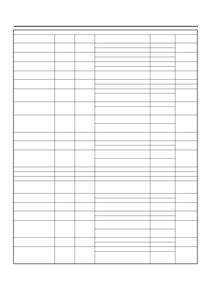
Check with ignition switch ON.
Content
Connector
No.
Terminal
No.
Measuring conditions
Voltage (V)
Resistance to
body (ohms)
AT-16
AUTOMATIC TRANSMISSION (DIAGNOSTICS)
TRANSMISSION CONTROL MODULE (TCM) I/O SIGNAL
Transfer duty solenoid
(VDC system or sport shift
equipped vehicle)
B54
6
Wide open throttle condition
More than 8.5
10 — 17
Wide open throttle condition
Less than 0.5
2-4 brake duty solenoid
B54
18
Throttle fully closed (with engine
OFF) after warm-up.
1.5 — 4.0
2.0 — 4.5
Throttle fully open (with engine OFF)
after warm-up.
Less than 0.5
2-4 brake timing solenoid
B54
16
1st gear
Less than 1
10 — 16
3rd gear
More than 9
Low clutch timing solenoid
B54
15
2nd gear
Less than 1
10 — 16
4th gear
More than 9
Hold switch
B55
16
Hold switch ON
Less than 1
—
Hold switch OFF
More than 8
—
Power switch
B55
23
Power switch ON
Less than 1
—
Power switch OFF
More than 10
—
Power indicator light
B56
11
Light ON
Less than 1
—
Light OFF
More than 9
—
FWD switch
(Without VDC system and
SPORT shift)
B55
20
Fuse removed
6 — 9.1
—
Fuse installed
Less than 1
—
FWD indicator light
(Without VDC system and
SPORT shift)
B56
2
Fused ON FWD switch
Less than 1
—
Fuse removed from FWD switch
More than 9
—
ABS signal
(Without VDC system and
SPORT shift)
B55
21
ABS switch ON
Less than 1
—
ABS switch OFF
6.5 — 15
—
Sensor ground line 1
B54
20
—
0
Less than 1
Sensor ground line 2
B55
9
—
0
Less than 1
System ground line
B56
19
—
0
Less than 1
B54
21
Sensor ground line 3
B54
10
—
0
Less than 1
Sensor ground line 4
B54
19
—
0
Less than 1
AT diagnosis signal
(Waveform)
B56
21
Ignition switch ON
Less than 1
←
→
More than 4
—
Data link signal
(Subaru Select Monitor)
B56
15
—
—
—
SPORT shift solenoid
(with SPORT shift)
B54
14
SPORT shift activated
More than 8
10 — 17
SPORT shift deactivated
Less than 1
SPORT shift mode switch
(with SPORT shift)
B55
15
SPORT shift mode switch ON
Less than 1
—
SPORT shift mode switch OFF
More than 8
Shift up switch
(with SPORT shift)
B55
13
Shift up switch ON
Less than 1
—
Shift up switch OFF
More than 8
Shift down switch
(with SPORT shift)
B55
12
Shift down switch ON
Less than 1
—
Shift down switch OFF
More than 8
Buzzer (with SPORT shift)
B56
21
ON
Less than 1
—
OFF
More than 8
SPORT shift indicator
(with SPORT shift)
B56
12
SPORT shift mode OFF
More than 4
—
Shift down indicator ON
Less than 1
SPORT shift indicator
(with SPORT shift)
B56
13
SPORT shift mode OFF
More than 4
—
SPORT shift mode with 4th gear
Less than 1
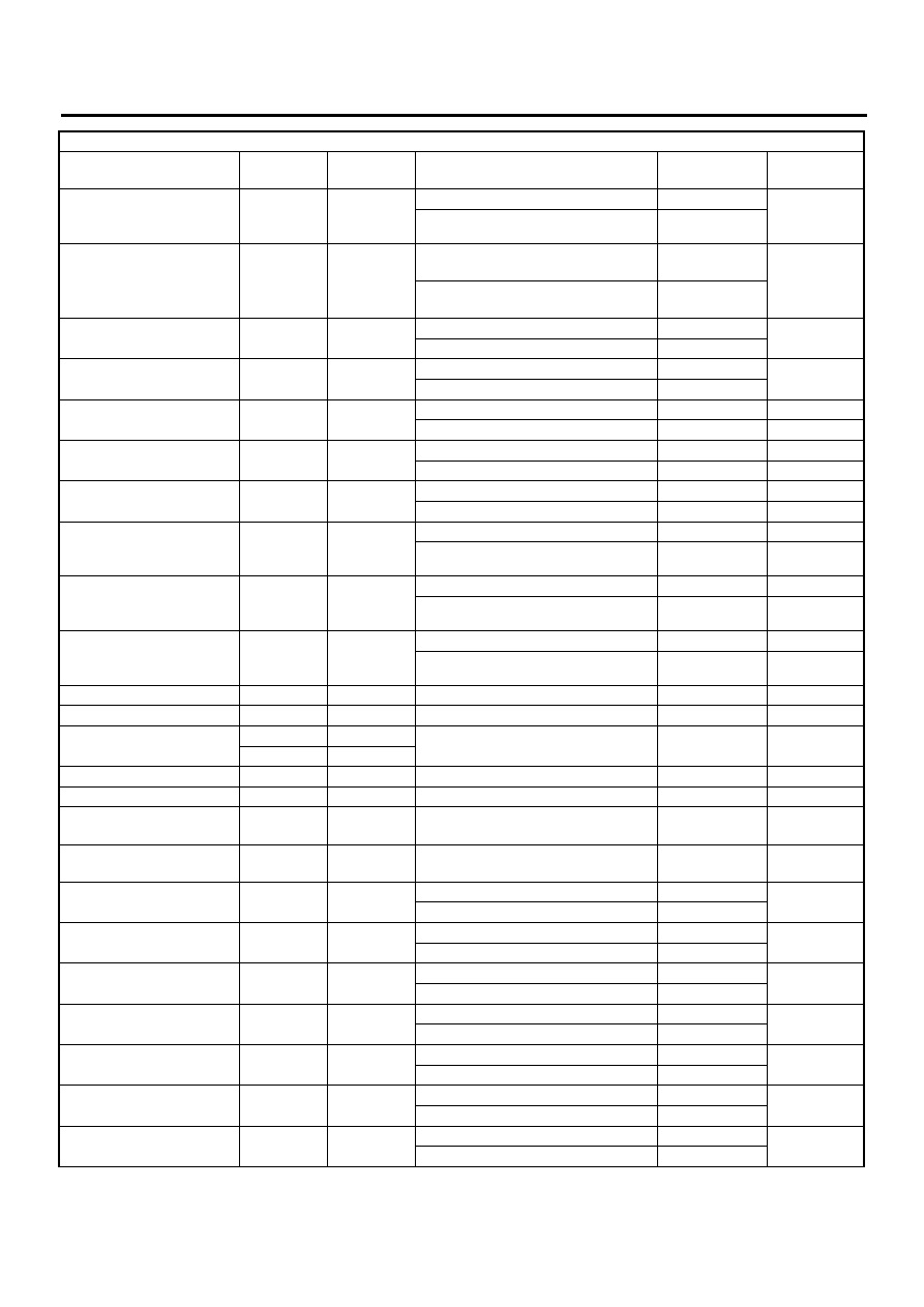
Check with ignition switch ON.
Content
Connector
No.
Terminal
No.
Measuring conditions
Voltage (V)
Resistance to
body (ohms)

AT-17
AUTOMATIC TRANSMISSION (DIAGNOSTICS)
TRANSMISSION CONTROL MODULE (TCM) I/O SIGNAL
SPORT shift indicator
(with SPORT shift)
B56
3
SPORT shift mode OFF
More than 4
—
SPORT shift mode with 2nd and 3rd
gear
Less than 1
SPORT shift indicator
(with SPORT shift)
B56
4
SPORT shift mode OFF
More than 4
—
SPORT shift mode with 1st and 3rd
gear
Less than 1
Check with ignition switch ON.
Content
Connector
No.
Terminal
No.
Measuring conditions
Voltage (V)
Resistance to
body (ohms)
Нет комментариевНе стесняйтесь поделиться с нами вашим ценным мнением.
Текст