Subaru Legacy III (2000-2003 year). Service manual — part 698
ABS-10
ABS (DIAGNOSTICS)
ELECTRICAL COMPONENTS LOCATION
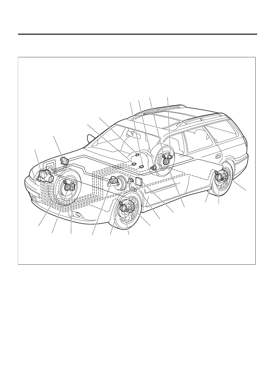
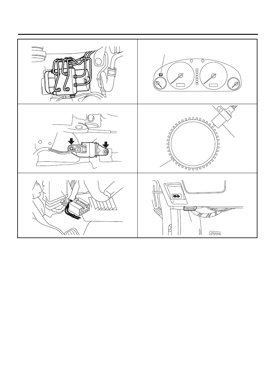
4. Electrical Components Location
A: LOCATION
(1) ABS control module and hydrau-
lic control unit (ABSCM&H/U)
(5) Data link connector (for Subaru
select monitor)
(8) ABS sensor
(9) Wheel cylinder
(2) Proportioning valve
(6) Transmission control module (only
AT vehicle)
(10) G sensor
(3) Diagnosis connector
(11) Stop light switch
(4) ABS warning light
(7) Tone wheel
(12) Master cylinder
ABS00281
( 9 )
( 8 )
( 5 )
( 4 )
( 3 )
( 2 )
( 1 )
( 9 )
( 7 )
( 8 )
( 7 )
( 6 )
( 9 )
( 7 )
( 8 )
( 9 )
( 7 )
( 8 )
(11)
(12)
(10)
ABS-11
ABS (DIAGNOSTICS)
ELECTRICAL COMPONENTS LOCATION
ABS00302
( 1 )
ABS00305
( 4 )
(10)
ABS00303
ABS00306
( 7 )
( 8 )
ABS00304
( 3 )
( 5 )
ABS00307
ABS-12
ABS (DIAGNOSTICS)
CONTROL MODULE I/O SIGNAL
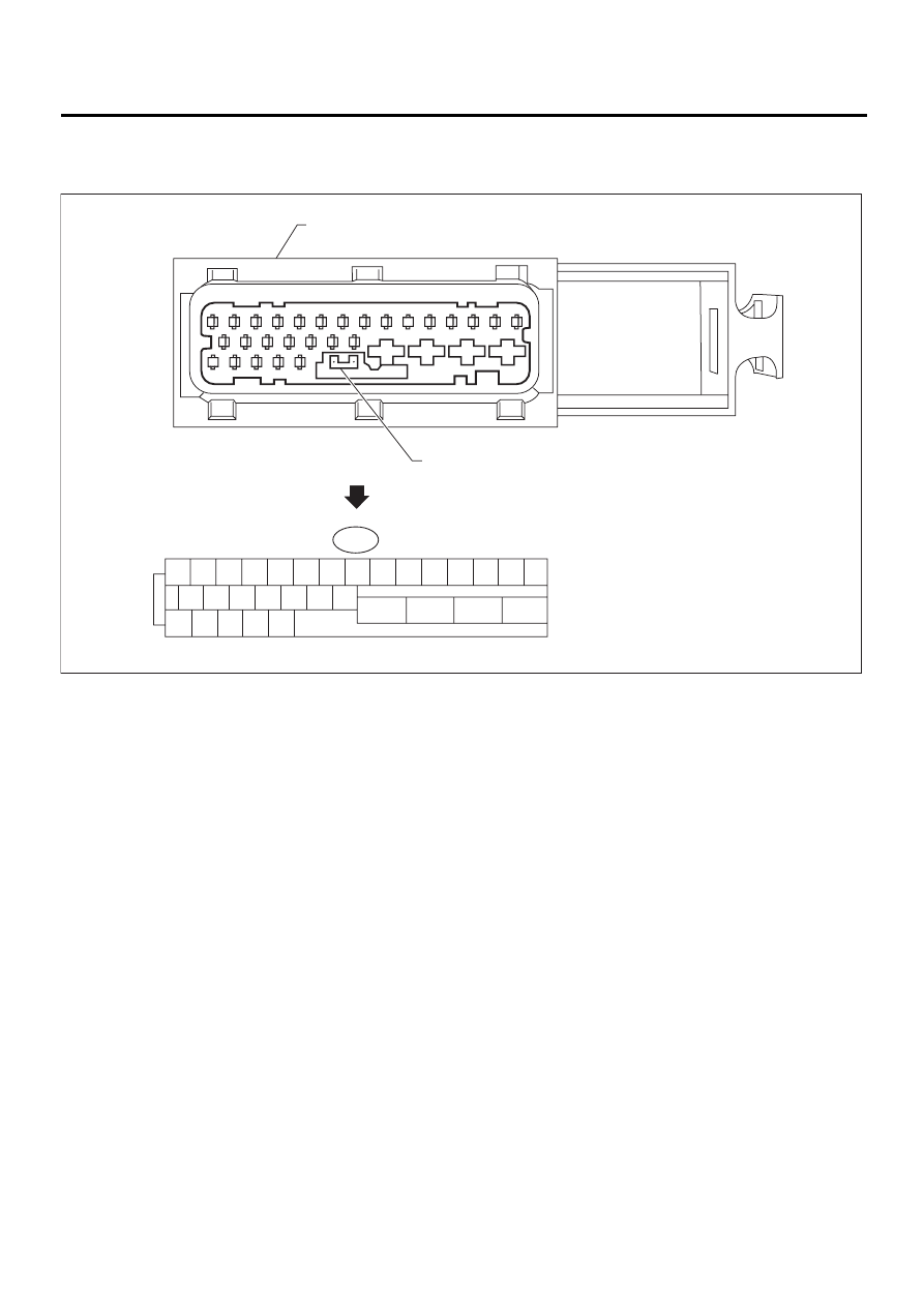
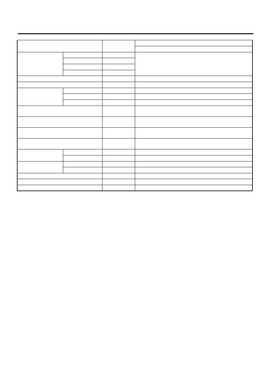
5. Control Module I/O Signal
A: ELECTRICAL SPECIFICATION
NOTE:
• The terminal numbers in the ABS control module and hydraulic control unit connector are as shown in the
figure.
• When the connector is removed from the ABSCM&H/U, the connector switch closes the circuit between
terminal No. 22 and No. 23. The ABS warning light illuminates.
(1) ABSCM&HU connector
(2) Connector switch
ABS00288
1 2 3 4 5 6 7 8 9 10 11
16 17 18 19 20 21 22
23
24
25
26
27 28 29 30 31
12 13 14 15
F49
( 1 )
( 2 )
ABS-13
ABS (DIAGNOSTICS)
CONTROL MODULE I/O SIGNAL
*1: Measure the I/O signal voltage after removing the connector from the ABSCM&H/U terminal.
*2: Measure the I/O signal voltage at connector (B62) or (F55).
Contents
Terminal No.
(+)—(
−
)
Input/Output signal
Measured value and measuring conditions
ABS sensor*2
(Wheel speed sensor)
Front left wheel
9—10
0.12 — 1 V
(When it is 20 Hz.)
Front right wheel
11—12
Rear left wheel
7—8
Rear right wheel
14—15
Valve relay power supply
24—23
10 — 15 V
Motor relay power supply
25—23
10 — 15 V
G sensor*2
power supply
30—28
4.75 — 5.25 V
ground
28
—
output
6—28
2.3
±
0.2 V when vehicle is in horizontal position.
Stop light switch*1
2—23
Less than 1.5 V when the stop light is OFF and, 10 — 15 V
when the stop light is ON.
ABS warning light*2
22—23
Less than 1.5 V during 1.5 seconds when ignition switch is ON,
and 10 — 15 V after 1.5 seconds.
AT ABS signal*2
(AT model only)
31—23
Less than 1.5 V when the ABS control still operates and more
than 5.5 V when ABS does not operate.
ABS operation signal monitor*2
3—23
Less than 1.5 V when the ABS control still operates and more
than 5.5 V when ABS does not operate.
Select monitor*2
Data is received.
20—23
Less than 1.5 V when no data is received.
Data is sent.
5—23
4.75 — 5.25 V when no data is sent.
ABS diagnosis connec-
tor*2
Terminal No. 3
29—23
10 — 15 V when ignition switch is ON.
Terminal No. 6
4—23
10 — 15 V when ignition switch is ON.
Power supply*1
1—23
10 — 15 V when ignition switch is ON.
Grounding line
23
—
Grounding line
26
—
Нет комментариевНе стесняйтесь поделиться с нами вашим ценным мнением.
Текст