Subaru Legacy III (2000-2003 year). Service manual — part 139
EN(H4SO)-168
ENGINE (DIAGNOSTICS)
DIAGNOSTIC PROCEDURE WITH DIAGNOSTIC TROUBLE CODE (DTC)
AF:DTC P0304 — CYLINDER 4 MISFIRE DETECTED —
• DTC DETECTING CONDITION:
• Two consecutive driving cycles with fault
• Immediately at fault recognition (A misfire which could damage catalyst occurs.)
• TROUBLE SYMPTOM:
• Engine stalls.
• Erroneous idling
• Rough driving
CAUTION:
After repair or replacement of faulty parts, conduct Clear Memory Mode<Ref. to EN(H4SO)-47, OPER-
ATION, Clear Memory Mode.> and Inspection Mode <Ref. to EN(H4SO)-40, OPERATION, Inspection
Mode.> .
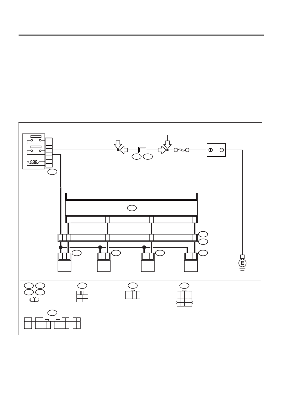
• WIRING DIAGRAM:
EN-01121
F44
B61
6
RHD
RHD
B22
1 2 3 4
5 6 7 8
9 10 11 12
13 14 15 16
E6
E17
E5
E16
1 2
1
2
1
2
1
2
1
2
22
23
34
8
9
1
10
11
12
ECM
B134
E5
E16
E6
E17
B22
E3
FUEL INJECTOR
No. 1
FUEL INJECTOR
No. 2
FUEL INJECTOR
No. 3
FUEL INJECTOR
No. 4
BATTERY
B134
1 2
3 4
5 6
7 8
9 10 11 12 13 14 15 16 17 18 19 20 21 22 23
24 25
26 27 28 29
30 31 32 33
34 35
SBF-5
B47
MAIN RELAY
1
2
3
5
4
6
B47
3
4
1
2
5
6
F44
1 2 3 4
5 6 7 8
LHD
LHD

EN(H4SO)-169
ENGINE (DIAGNOSTICS)
DIAGNOSTIC PROCEDURE WITH DIAGNOSTIC TROUBLE CODE (DTC)
Step
Value
Yes
No
1
CHECK ANY OTHER DTC ON DISPLAY.
Is any other DTC displayed?
DTC indicated.
Inspect the rele-
vant DTC using
“List of Diagnostic
Trouble Code
(DTC)”. <Ref. to
EN(H4SO)-83, List
of Diagnostic
Trouble Code
(DTC).>
NOTE:
In this case, it is
not necessary to
inspect DTC
P0301, P0302,
P0303 and P0304.
2
CHECK OUTPUT SIGNAL FROM ECM.
1) Turn ignition switch to ON.
2) Measure voltage between ECM connector
and chassis ground on faulty cylinders.
Connector & terminal
#1 (B134) No. 34 (+) — Chassis ground
(
−−−−
):
#2 (B134) No. 23 (+) — Chassis ground
(
−−−−
):
#3 (B134) No. 22 (+) — Chassis ground
(
−−−−
):
#4 (B134) No. 8 (+) — Chassis ground
(
−−−−
):
Does the measured value exceed the spec-
ified value?
10 V
3
CHECK HARNESS BETWEEN FUEL INJEC-
TOR AND ECM CONNECTOR.
1) Turn ignition switch to OFF.
2) Disconnect connector from fuel injector on
faulty cylinders.
3) Measure voltage between ECM connector
and engine ground on faulty cylinders.
Connector & terminal
#1 (E5) No. 1 — Engine ground:
#2 (E16) No. 1 — Engine ground:
#3 (E6) No. 1 — Engine ground:
#4 (E17) No. 1 — Engine ground:
Is the measured value less than the speci-
fied value?
10
Ω
Repair ground
short circuit in har-
ness between fuel
injector and ECM
connector.
4
CHECK HARNESS BETWEEN FUEL INJEC-
TOR AND ECM CONNECTOR.
Measure resistance of harness connector
between ECM connector and fuel injector on
faulty cylinders.
Connector & terminal
#1 (B134) No. 34 — (E5) No. 1:
#2 (B134) No. 23 — (E16) No. 1:
#3 (B134) No. 22 — (E6) No. 1:
#4 (B134) No. 18 — (E17) No. 1:
Is the measured value less than the specified
value?
1
Ω
Repair harness
and connector.
NOTE:
In this case, repair
the following:
• Open circuit in
harness between
ECM and fuel
injector connector
• Poor contact in
coupling connector

EN(H4SO)-170
ENGINE (DIAGNOSTICS)
DIAGNOSTIC PROCEDURE WITH DIAGNOSTIC TROUBLE CODE (DTC)
5
CHECK FUEL INJECTOR.
Measure resistance between fuel injector ter-
minals on faulty cylinder.
Terminals
No. 1 — No. 2:
Is the measured value within the specified
range?
5 - 20
Ω
Replace faulty fuel
injector. <Ref. to
FU(H4SO)-36,
Fuel Injector.>
6
CHECK POWER SUPPLY LINE.
1) Turn ignition switch to ON.
2) Measure voltage between fuel injector and
engine ground on faulty cylinders.
Connector & terminal
#1 (E5) No. 2 (+) — Engine ground (
−−−−
):
#2 (E16) No. 2 (+) — Engine ground (
−−−−
):
#3 (E6) No. 2 (+) — Engine ground (
−−−−
):
#4 (E17) No. 2 (+) — Engine ground (
−−−−
):
Does the measured value exceed the spec-
ified value?
10 V
Repair poor con-
tact in all connec-
tors in fuel injector
circuit.
Repair harness
and connector.
NOTE:
In this case, repair
the following:
• Open circuit in
harness between
main relay and fuel
injector connector
on faulty cylinders
• Poor contact in
coupling connector
• Poor contact in
main relay con-
nector
• Poor contact in
fuel injector con-
nector on faulty
cylinders
7
CHECK HARNESS BETWEEN FUEL INJEC-
TOR AND ECM CONNECTOR.
1) Turn ignition switch to OFF.
2) Disconnect connector from fuel injector on
faulty cylinder.
3) Turn ignition switch to ON.
4) Measure voltage between ECM connector
and chassis ground on faulty cylinders.
Connector & terminal
#1 (B134) No. 34 (+) — Chassis ground
(
−−−−
):
#2 (B134) No. 23 (+) — Chassis ground
(
−−−−
):
#3 (B134) No. 22 (+) — Chassis ground
(
−−−−
):
#4 (B134) No. 8 (+) — Chassis ground
(
−−−−
):
Does the measured value exceed the spec-
ified value?
10 V
Repair battery
short circuit in har-
ness between
ECM and fuel
injector. After
repair, replace
ECM. <Ref. to
FU(H4SO)-45,
Engine Control
Module.>
8
CHECK FUEL INJECTOR.
1) Turn ignition switch to OFF.
2) Measure resistance between fuel injector
terminals on faulty cylinder.
Terminals
No. 1 — No. 2:
Is the measured value less than the speci-
fied value?
1
Ω
Replace faulty fuel
injector <Ref. to
FU(H4SO)-36,
Fuel Injector.> and
replacce ECM
<Ref. to
FU(H4SO)-45,
Engine Control
Module.>
9
CHECK INSTALLATION OF CAMSHAFT PO-
SITION SENSOR/CRANKSHAFT POSITION
SENSOR.
Is camshaft position sensor or crankshaft posi-
tion sensor loosely installed?
Loosely installed.
Tighten camshaft
position sensor or
crankshaft posi-
tion sensor.
Step
Value
Yes
No

EN(H4SO)-171
ENGINE (DIAGNOSTICS)
DIAGNOSTIC PROCEDURE WITH DIAGNOSTIC TROUBLE CODE (DTC)
10
CHECK CRANKSHAFT SPROCKET.
Remove timing belt cover.
Is crankshaft sprocket rusted or does it have
broken teeth?
Rusted sprocket or broken
teeth.
Replace crank-
shaft sprocket.
<Ref. to
ME(H4SO)-53,
Crankshaft
Sprocket.>
11
CHECK INSTALLATION CONDITION OF
TIMING BELT.
Turn crankshaft using ST, and align alignment
mark on crankshaft sprocket with alignment
mark on cylinder block.
Is timing belt dislocated from its proper posi-
tion?
Dislocated from its proper posi-
tion.
Repair installation
condition of timing
belt. <Ref. to
ME(H4SO)-46,
Timing Belt
Assembly.>
12
CHECK FUEL LEVEL.
Is the fuel meter indication higher than the
“Lower” level?
Indicated higher than the
"Lower" level.
Replenish fuel so
fuel meter indica-
tion is higher than
the “Lower” level.
After replenishing
fuel, Go to step 13.
13
CHECK STATUS OF CHECK ENGINE MAL-
FUNCTION INDICATOR LAMP (MI).
1) Clear memory using Subaru Select Moni-
tor.
<Ref. to EN(H4SO)-47, Clear Memory
Mode.>
2) Start engine, and drive the vehicle more
than 10 minutes.
Is the MI coming on or blinking?
The MI is coming on or blink-
ing.
Step
Value
Yes
No
Нет комментариевНе стесняйтесь поделиться с нами вашим ценным мнением.
Текст