Subaru XV Crosstrek Hybrid (2016 year). Manual — part 11
Instruments and controls/Warning and indicator lights
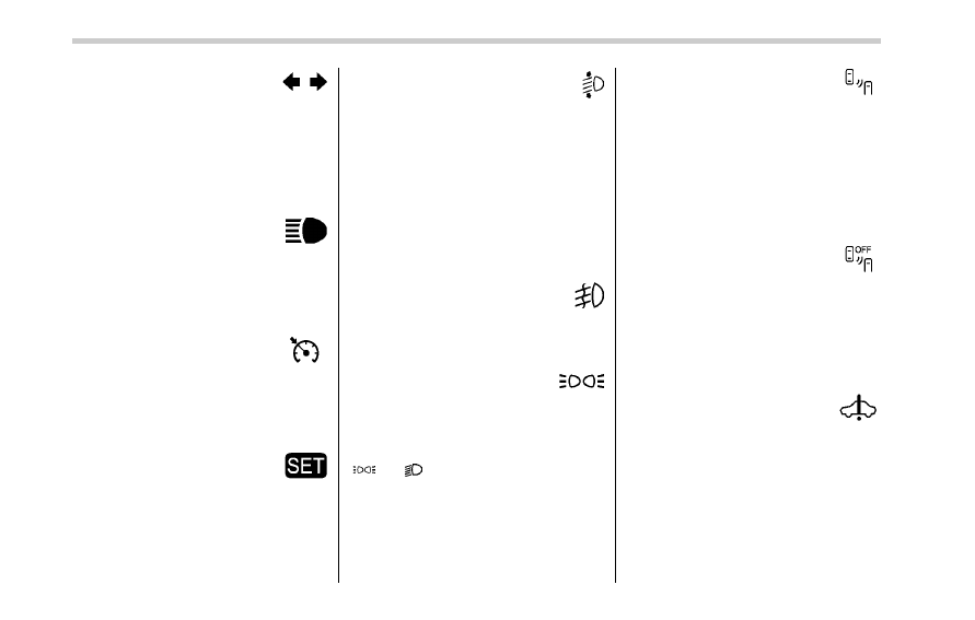
&
Turn signal indicator
lights
These lights show the operation of the turn
signal or lane change signal.
If the indicator lights do not blink or blink
rapidly, the turn signal bulb may be burned
out. Replace the bulb as soon as possible.
Refer to
“Replacing bulbs” F11-39.
&
High beam indicator
light
This light shows that the headlights are in
the high beam mode.
This indicator light also illuminates when
the headlight flasher is operated.
&
Cruise control indica-
tor light
This light illuminates when the cruise
control main button is pressed to activate
the cruise control function. For details,
refer to
“To set cruise control” F7-33.
&
Cruise control set in-
dicator light
This light illuminates when vehicle speed
has been set to use the cruise control
function. Refer to
“To set cruise control”
F7-33.
&
Automatic headlight
beam leveler warning
light (models with HID
headlights)
This light illuminates when the automatic
headlight beam leveler does not operate
normally.
If this light illuminates while driving or does
not turn off approximately 3 seconds after
turning the ignition switch to the
“ON”
position, have your vehicle inspected at
your SUBARU dealer.
&
Front fog light indicator
light (if equipped)
This indicator light illuminates while the
front fog lights are illuminated.
&
Headlight indicator
light (if equipped)
This indicator light illuminates under the
following conditions.
. when the light switch is turned to the
“
” or “ ” position
. when the light control switch is in the
“AUTO” position and the headlights illumi-
nate automatically
&
BSD/RCTA warning in-
dicator (if equipped)
This warning indicator illuminates or
flashes when the BSD/RCTA is malfunc-
tioning. In this case the BSD/RCTA warn-
ing indicator will be shown on the combi-
nation meter. When this indicator is flash-
ing or illuminated for a prolonged time,
have your vehicle inspected by your
SUBARU dealer as soon as possible.
&
BSD/RCTA OFF indica-
tor (if equipped)
The indicator illuminates when the BSD/
RCTA OFF switch is pressed to deactivate
the BSD/RCTA. In this case the BSD/
RCTA OFF indicator will be shown on the
combination meter. For details, refer to
“BSD/RCTA” F7-37.
&
Hybrid Fail Lamp
The Hybrid Fail Lamp illuminates when a
malfunction occurs in the hybrid system.
3-28
CAUTION
When the Hybrid Fail Lamp is illu-
minated, an interruption screen will
be displayed simultaneously on the
multi function display. Perform the
procedure shown on the multi func-
tion display, then have your vehicle
inspected by a SUBARU dealer im-
mediately.
&
Pedestrian alert warn-
ing light
This light illuminates when a malfunction
occurs in the pedestrian alert system.
&
Hybrid READY Indica-
tor Light
This light illuminates when the hybrid
system has started. It turns off when the
hybrid system has been turned off.
CAUTION
If the Hybrid READY Indicator Light
does not illuminate when the engine
has been started, have your vehicle
checked at a SUBARU dealer.
&
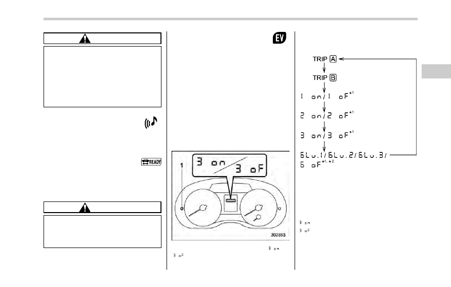
EV (Electric Vehicle)
mode lamp
This light illuminates in the following
cases.
. When driving only using the electric
motor power
. When the engine is automatically
stopped by the hybrid system
! Activation/deactivation settings
The EV (Electric Vehicle) mode lamp can
be activated or deactivated. To change the
setting, perform the following procedure.
1. Turn the ignition switch to the
“LOCK”
or
“ACC” position.
2. Press the trip knob to show
“
” or
“
” on the trip meter display.
The display can be switched as shown in
the following sequence by pressing the
trip knob.
*1: Cannot be displayed when the ignition
switch is in the
“ON” position.
*2: Displayed only for models with BSD/
RCTA.
To change the current setting, press the
trip knob for at least 2 seconds.
: Activated
: Deactivated
Instruments and controls/Warning and indicator lights
– CONTINUED –
3-29
Instruments and controls/Multi function display
NOTE
Your vehicle
’s initial setting has been
set for activation
“
” at the time of
shipment from the factory.
Multi function display
& Safety precautions
WARNING
Always pay adequate attention to
safe driving when operating the
multi function display while the
vehicle is in motion. When operation
of the multi function display is
disturbing your awareness and abil-
ity to concentrate on driving, stop
the vehicle in a safe place before
performing operations on the
screen. Also, do not concentrate
on the display while driving. Doing
so may cause you to look away from
the road and could result in an
accident.
& Features
The multi function display has the follow-
ing functions.
Description
Page
Displays useful messages, such
as warning information, etc.
3-34
Displays basic screens (e.g. fuel
consumption screen, etc.)
3-34
Sets and adjusts maintenance
notification
3-61
Registers driving history
3-64
Sets and customizes car opera-
tion
3-65
Also, the multi function display can also be
used to set and initialize the multi function
display itself.
NOTE
When the vehicle is in motion, certain
functions and selections may not be
available.
3-30
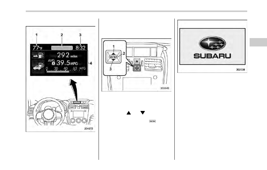
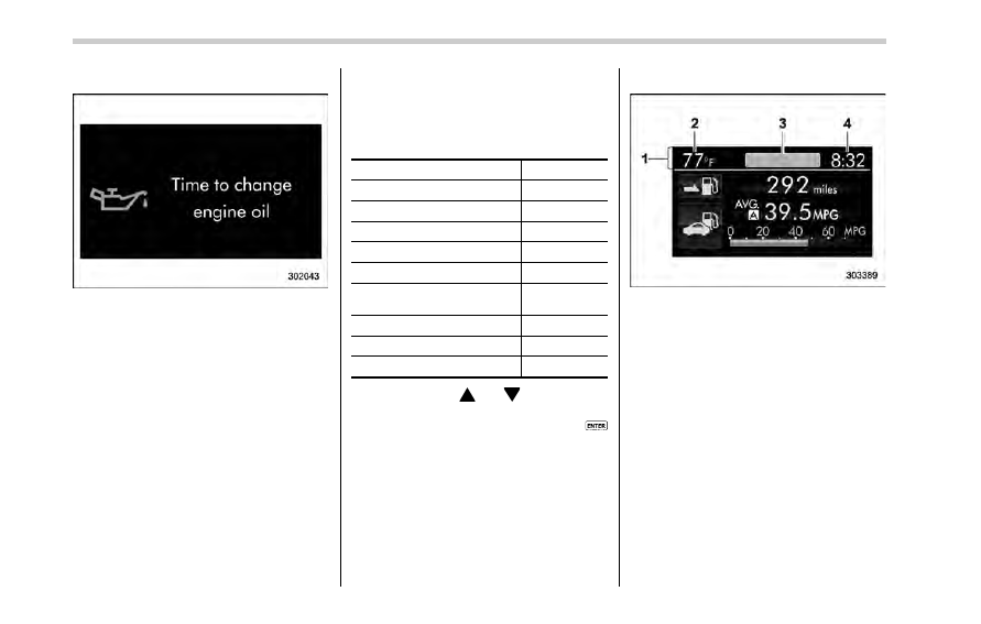
& Locations
Multi function display
1)
Outside temperature indicator
2)
Top display (For the display setting, refer
to
“Top display setting” F3-53.)
3)
Clock
4)
Driving information display (For the dis-
played contents, refer to
“Basic screens”
F3-34.)
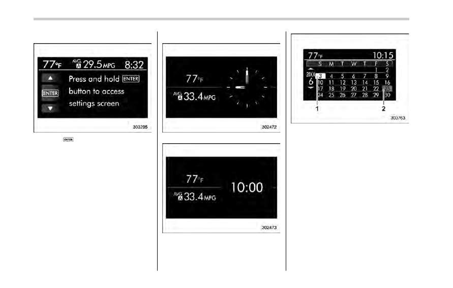
& Basic operation
Control switch
1)
Up (select)
2)
ENTER (push)
3)
Down (select)
By operating
“ ” or “ ” of the control
switch, the screens and selection items
can be switched. When the
button is
pushed, the item can be selected and set.
& Welcome screen
When the door is unlocked and the
driver
’s door is closed, the welcome
screen will appear for a short time.
NOTE
. The welcome screen will disappear
when the ignition switch is turned to
the
“ON” position while the welcome
screen is displayed.
. The welcome screen can be set to
on or off. For details, refer to
“Bypass
screen setting
” F3-59.
. For a certain period of time after the
welcome screen has once appeared, it
may not appear again even when the
driver
’s door is closed again. This does
not indicate a malfunction.
Instruments and controls/Multi function display
– CONTINUED –
3-31
Instruments and controls/Multi function display
& Date screen
If you have set the date and time in the
selection screen, after the welcome
screen is displayed, the current date will
be displayed for a certain period of time. If
“On/Off setting” is set to “On” in the
“Maintenance settings”, the date screen
will be displayed after the self-check
screen.
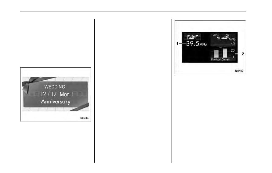
! Birthday/anniversary screen
Example of notification on an anniversary
If you have set a birthday or anniversary,
after the date screen is displayed, the
notification (reminder) will be displayed for
a certain period of time from 7 days prior
to the set date.
NOTE
. Displaying the birthday/anniversary
screen can be set to on or off. Refer to
“Bypass screen setting” F3-59.
. Up to five items can be set for
birthdays and anniversaries respec-
tively. Refer to
“Selection screen” F3-
41.
& Ending screen
If
“Eco Summary” is set to “On” in the
“Bypass screen setting”, the “Fuel con-
sumption results screen
” will be displayed
before the screen turns off when the
ignition switch is turned to the
“OFF”
position.
Fuel consumption results screen
1)
The average fuel consumption for the
entire driving distance, from when the
ignition switch was turned to the
“ON”
position to when it was turned to the
“OFF” position.
2)
This display shows the average rate of
fuel consumption since the trip meter
was last reset. It displays the average
fuel consumption corresponding to the A
trip meter mileage or the one corre-
sponding to the B trip meter mileage.
& Self-check screen
When the ignition switch is turned to the
“ON” position, the vehicle self-check will
be performed. The screens corresponding
to the following items will appear one after
another for several seconds each.
3-32
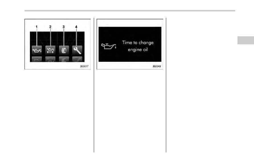
1)
Engine oil: Checks the interval of engine
oil replacement.
2)
Oil filter: Checks the interval of oil filter
replacement.
3)
Tires: Checks the interval of tire rotation.
4)
Inspection and maintenance: Checks the
interval of inspection and maintenance.
When the checks are performed, the color
of the icon corresponding to the checked
item will turn green.
If there is no warning message, the self-
check will complete without notification.
Example of notification
If there is a warning message or a
maintenance notification, the color of the
icon corresponding to the item will turn
yellow and the warning message or the
maintenance notification will be displayed.
Take the appropriate actions based on the
messages indicated.
NOTE
. The self-check screen can be set to
on or off. For details, refer to
“On/Off
setting
” F3-62.
. After performing the maintenance,
change the setting of the correspond-
ing maintenance item. For details, refer
to
“Maintenance settings” F3-61.
. The maintenance notification screen
will be displayed under either of the
following conditions.
– The period of time remaining
until the registered notification date
is 15 days or less.
– The total driving distance remain-
ing until the registered notification
distance is approximately 311 miles
(500 km) or less.
. The maintenance notification screen
will be displayed until either of the
following conditions is satisfied.
– The period of time passed after
the registered notification date is 15
days or more.
– The total distance driven after the
registered notification distance is
approximately 311 miles (500 km) or
more.
Instruments and controls/Multi function display
– CONTINUED –
3-33
Instruments and controls/Multi function display
& Interruption screen
Warning information (display example)
Useful messages, such as reminder in-
formation, vehicle information, warning
information, etc. may interrupt the current
screen and appear on the display accom-
panied by a beep. Take proper action
according to the message.
The warning screen will return to the
original screen after a few seconds.
& Basic screens
! Basic screen items
These are the basic screens of the multi
function display.
Item
Page
Information bar
3-34
Fuel consumption screen
3-36
ECO history screen
3-36
Fuel save screen
3-37
Energy flow screen
3-37
Vehicle activation status
screen
3-38
Triple meter screen
3-39
Guidance screen
3-40
Clock/calendar screen
3-40
By operating the
“ ” or “ ” of the control
switch, you can switch the screen that is
always displayed. Also, when the
button is pushed and held, the selection
screen can be displayed. For details about
the selection screen, refer to
“Selection
screen
” F3-41.
! Information bar
1)
Information bar
2)
Outside temperature indicator
3)
Top display
4)
Clock
While the ignition switch is in the
“ACC” or
“ON” position, the outside temperature
indicator, clock, etc. will be shown on the
information bar.
! Outside temperature indicator
This displays the outside temperature
between
−408F (−408C) and 1228F
(50
8C).
3-34
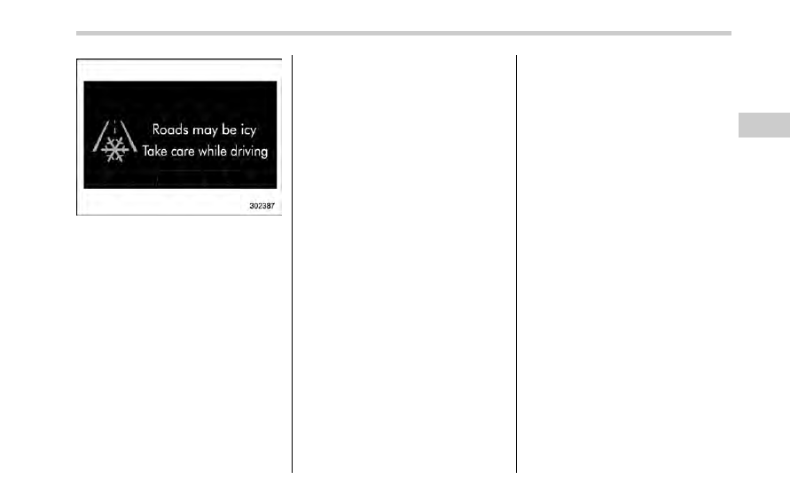
Icy road surface warning screen
When the outside temperature becomes
37
8F (38C) or less, the icy road surface
warning screen interrupts to inform the
driver that the road surface may be frozen.
NOTE
. The outside temperature indicator
shows the temperature around the
sensor. Therefore, the temperature in-
dication may differ from the actual
outside air temperature.
. The icy road surface warning screen
should be treated only as a guide. Be
sure to check the condition of the road
surface before driving.
. Once the icy road surface warning
screen is displayed, it will not be
displayed again unless the ignition
switch is turned to the
“ACC” or “ON”
position after it has been turned to
“OFF” position.
! Information reminder
The screen returns to the original screen
several seconds after the interruption
screen has been displayed. If the inter-
ruption screen can be displayed once
more even after the original screen has
appeared, an information reminder should
be displayed. For details about the inter-
ruption screen, refer to
“Interruption
screen
” F3-34.
! Top display
One of the following items can be dis-
played on the top display.
. Average fuel consumption correspond-
ing to the driving distance of each trip
meter
. Current fuel consumption (This may
not be displayed when driving at a low
speed.)
. Driving range on remaining fuel
For details about the setting of the top
display, refer to
“Top display setting” F3-
53.
NOTE
The driving range on the remaining fuel
is calculated using the average fuel
consumption of the last 19 miles (30
km) driven. This value may be different
from the values calculated using the
average fuel consumption correspond-
ing to the driving distance of each trip
meter or the current fuel consumption.
! Clock
The clock can be displayed in either 12-
hour display or 24-hour display. For details
about the setting, refer to
“Current date
and time setting
” F3-44.
NOTE
If the 12 V auxiliary battery is discon-
nected, the clock shown in the informa-
tion bar will be reset. Set the time again
after the 12 V auxiliary battery is
connected. For details about the
setting, refer to
“Top display setting”
F3-53.
Instruments and controls/Multi function display
– CONTINUED –
3-35
Instruments and controls/Multi function display
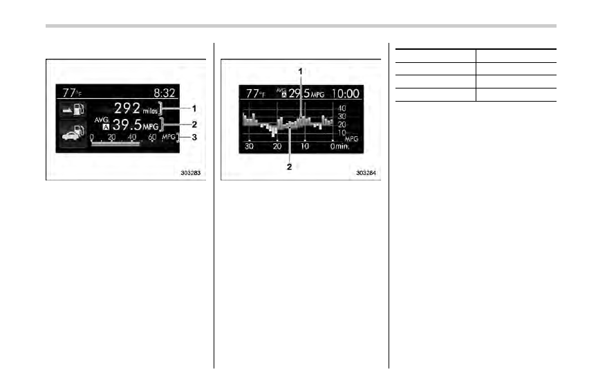
! Fuel consumption screen
1)
Driving range on remaining fuel
2)
Average fuel consumption corresponding
to the driving distance of each trip meter
3)
Current fuel consumption
The displayed location can be custo-
mized. For details, refer to
“Fuel consump-
tion screen setting
” F3-54.
! ECO history screen
1)
Average fuel consumption per unit time
(bar graph)
2)
Average fuel consumption corresponding
to the driving distance of each trip meter
(red line)
This screen displays the fuel economy
history for the vehicle using a bar graph.
The horizontal scale represents the past
time range and the vertical scale repre-
sents the fuel consumption. The green
bars show driving with good fuel economy
and the yellow bars show driving with poor
fuel economy.
The time range of the history can be set.
The width of the bar graph is adjusted as
follows depending on the set time range.
Time range
Width of bar graph
30 minutes
1 minute
60 minutes
2 minutes
120 minutes
4 minutes
For details about the setting, refer to
“Economy history setting” F3-55.
3-36
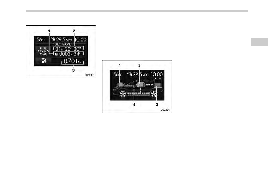
! Fuel save screen
This screen displays the following infor-
mation.
1)
The total time the engine was stopped by
the hybrid system, from the most recent
reset of the currently displayed trip meter
to the current time.
2)
The total time the engine was stopped by
the hybrid system, from the time that the
ignition switch was turned to the
“ON”
position to the current time.
3)
The total amount of fuel saved due to the
engine being stopped by the hybrid
system, from the most recent reset of the
currently displayed trip meter to the
current time.
NOTE
. When the trip meter is reset, the
corresponding accumulated time and
the amount of fuel saving are also
reset.
. The time spent with the engine
stopped by means of the hybrid system
is also added to the journey time.
! Energy flow screen
NOTE
For details, refer to
“Screen display”
F16.
This screen displays the following infor-
mation.
1)
Engine operation status display: When
the engine is in operation, the indicator
will illuminate in orange. When the
engine is stopped by the hybrid system,
the indicator will illuminate in gray. If the
ignition switch is turned to the
“OFF”
position, the indicator will switch off.
2)
Electric motor operation status display:
When generating, the indicator will illu-
minate in blue. When the electric motor is
in operation (except while generating) the
indicator will illuminate in green. When
the electric motor is not generating or the
electric motor is not in operation, the
indicator will illuminate in gray. If the
ignition switch is turned to the
“OFF”
position, the indicator will switch off.
3)
Remaining quantity of the high voltage
battery
4)
Energy flow display: This displays the
energy flow and the remaining power of
the high voltage battery. Power from the
engine will be displayed in orange, power
from the electric motor will be displayed
in green and the current of energy
charging the high voltage battery will be
displayed in aqua blue.
Instruments and controls/Multi function display
– CONTINUED –
3-37
Instruments and controls/Multi function display
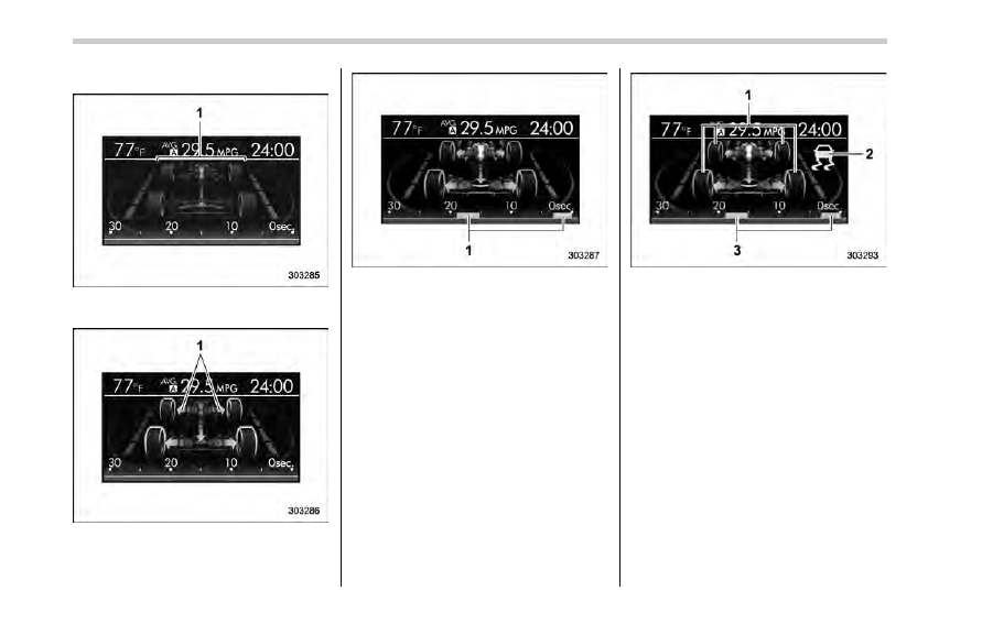
! Vehicle activation status screen
When the vehicle stops
1)
Steering axle
When the vehicle is being driven regularly
1)
Power train (illuminated in blue)
When the Vehicle Dynamics Control sys-
tem is being activated: the tires illuminate
in yellow.
1)
History of Vehicle Dynamics Control
system activation
When the Vehicle Dynamics Control sys-
tem has been activated: the tires remain
illuminated in yellow while the Vehicle
Dynamics Control System is activated.
1)
Activation status of the ABS (Anti-lock
Brake System)
2)
Vehicle Dynamics Control system oper-
ating indicator (flashing in yellow)
3)
History of Vehicle Dynamics Control
system activation
This screen displays the following vehicle
information.
. steering angle and driving wheel status
. activation status of the ABS (Anti-lock
Brake System)
. activation status of the Vehicle Dy-
namics Control system
While driving, the vehicle wheels are
illuminated in blue and the driving direc-
3-38
tion is represented using an animation of
the traffic lane.
If the ABS is activated, all of the vehicle
’s
wheels will be illuminated in yellow and
the length of operation in seconds and the
number of activations will be displayed in
the bar indicator, located on the lowermost
part of the display.
If the Vehicle Dynamics Control system is
activated, the activated vehicle wheels will
be illuminated in yellow and the operating
indicator
“ ” will appear on the upper right
part of the display. Also, the length of
operation in seconds and the number of
activations will be displayed in the bar
indicator.
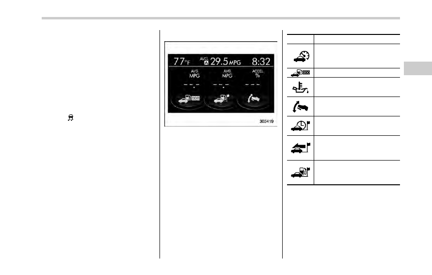
! Triple meter screen
Triple meter screen (display example)
This screen displays up to three optional
pieces of information that can be selected
from the following items.
The items shown in the triple meter screen
can be changed. For details, refer to
“Triple meter setting” F3-57.
Item
Details
Average vehicle speed (Average
vehicle speed for the entire driving
time from when the trip meter was
reset)
Lifetime fuel consumption
Engine oil temperature
Accelerator opening ratio
Journey time (the time that has
elapsed since the ignition switch
was turned to the
“ON” position)
Journey distance (the distance
that has been driven since the
ignition switch was turned to the
“ON” position)
Average fuel consumption for the
entire driving distance from when
the ignition switch was turned to
the
“ON” position
Instruments and controls/Multi function display
– CONTINUED –
3-39
Instruments and controls/Multi function display
! Guidance screen
When the
button is pushed and held,
the selection screen can be displayed.
The displayed contents can be set or
customized from the selection screen. For
details, refer to
“Selection screen” F3-41.
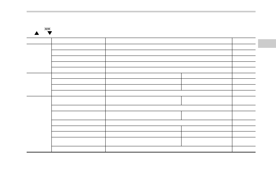
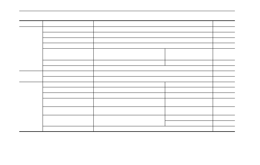
! Clock/calendar screen
Clock (analog format)
Clock (digital format)
Calendar
1)
Today
’s date
2)
Birthday/Anniversary
In addition to the clock/calendar, the out-
side temperature and average fuel con-
sumption can also be displayed.
You can select clock (analog format),
clock (digital format) or calendar. The
clock/calendar can also be set so that it
is not displayed. For details, refer to
“Clock/calendar screen setting” F3-58.
3-40
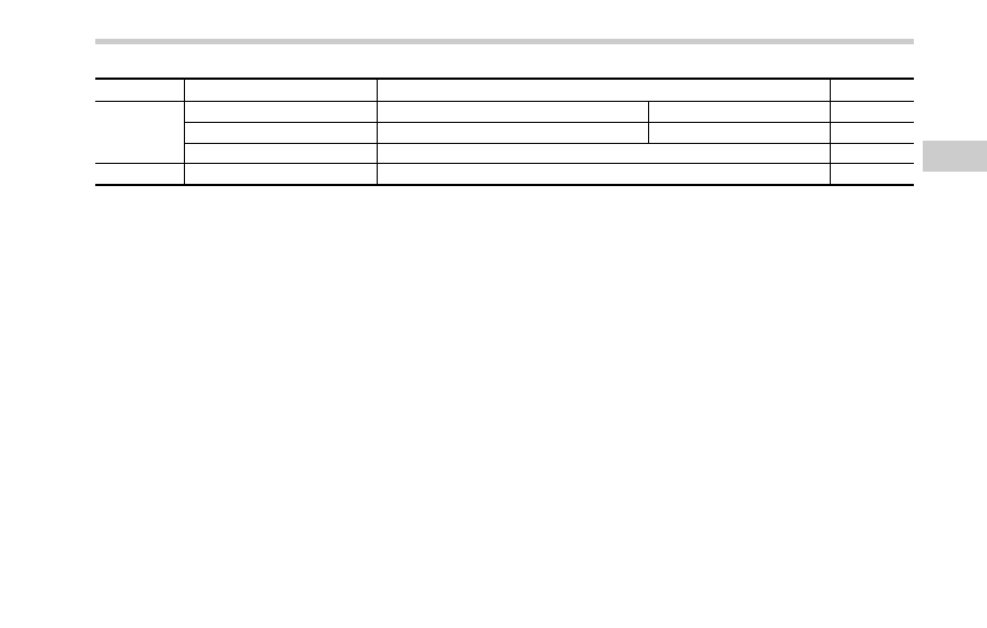
& Selection screen
When the
button is pushed and held, the setting screen for each menu can be displayed. Select the preferred menu by operating
the
“ ” or “ ” switch.
Top menu
Menu option
Description
Page
Time/Date
Time/Date
Set and adjust the time and date. 12h or 24h format can be selected.
3-44
Birthday
Set a birthday.
3-45
Anniversary
Set an anniversary day.
3-47
Daylight Saving Time
Turn the daylight saving time on or off
3-50
Go Back
Return to the top menu.
—
Display
Contrast
Adjust the contrast.
+5
↔ −5
3-51
Screen Off
Turn the screen on or off.
On or Off
3-51
Beep
Adjust the beep sound volume.
High, Low or Off
3-52
Go Back
Return to the top menu.
—
Screen Setting
Top Display
Set and customize the top display information
contents.
Avg Cons, Inst Cons, Range or
Off
3-53
Cons
Customize the fuel consumption information display.
3-54
Eco History
Set and customize the time of logging fuel
consumption history.
30 min, 60 min or 120 min
3-55
Triple Meter
Set and customize the triple meter.
3-57
Clock
Select the clock format.
Analog, Digital, Calendar or Off
3-58
Bypass Screen
Set the bypass screen for each item.
On or Off
3-59
Languages
Select the display language.
English or French or Spanish
(U.S.-spec. models only)
3-60
Go Back
Return to the top menu.
—
Instruments and controls/Multi function display
– CONTINUED –
3-41
Instruments and controls/Multi function display
Top menu
Menu option
Description
Page
Maintenance
Engine Oil
Set and adjust the oil maintenance notification date.
3-61
Oil Filter
Set and adjust the oil filter maintenance notification date.
3-62
Tires
Set and adjust the tire maintenance notification date.
3-62
Maintenance Schedule
Set and adjust the vehicle maintenance notification date.
3-62
On/Off
Turn on or off the self-check screen that is
activated when the ignition switch is turned to
the
“ON” position.
On or Off
3-62
Clear All Settings
Clear all settings for maintenance items.
Yes or No
3-63
Go Back
Return to the top menu.
—
Driving History Set
Register and overwrite the driving record.
3-64
Go Back
Return to the top menu.
—
Car Setting
Keyless Buzzer Volume
Set the audible signal volume.
0 (OFF) to 7
3-66
Hazard Warning Flasher
Set the hazard warning flasher.
On or Off
3-66
Defogger
Set and customize the operation of the defogger. 15 minutes or Continuous
3-67
Interior Light
Set and customize the interior light off delay
timer.
10, 20, 30 seconds or Off
3-69
Auto Light Sensor (if equipped)
Set and customize the sensitivity of the auto
light sensor.
Low, Mid, High or Max
3-70
Keyless Access Setting
Set and customize the keyless access function.
Driver
’s Door Unlock
3-71
Rear Gate Unlock
3-72
Go Back
Return to top menu.
—
3-42
Top menu
Menu option
Description
Page
Initialize
Reset to Defaults
Reset all settings to the default settings.
Yes or No
3-74
Lifetime Fuel Consumption Reset Clear logged lifetime fuel consumption data.
Yes or No
3-75
Go Back
Return to the top menu.
—
Go Back
—
Return to the top menu.
—
Instruments and controls/Multi function display
– CONTINUED –
3-43
Нет комментариевНе стесняйтесь поделиться с нами вашим ценным мнением.
Текст