Subaru XV Crosstrek Hybrid (2016 year). Manual — part 22
Interior equipment/Interior lights
Interior lights
CAUTION
When leaving your vehicle, make
sure the lights are turned off to
avoid battery discharge.
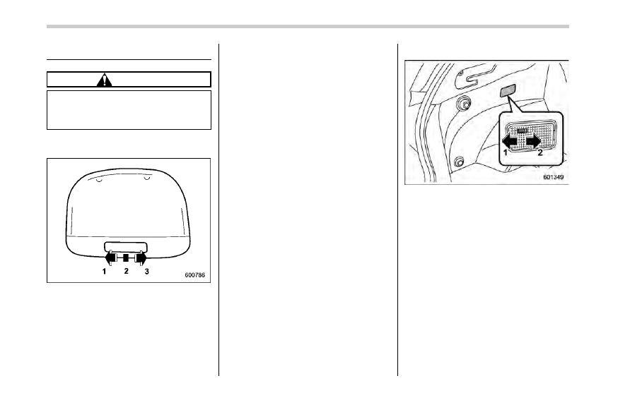
& Dome light
1)
ON
2)
DOOR
3)
OFF
The dome light switch has the following
positions.
ON: The light remains on continuously.
OFF: The light remains off.
DOOR: The dome light illuminates auto-
matically in the following cases.
. Any of the doors or the rear gate is
opened.
. The doors or the rear gate are un-
locked using the keyless access function.
Refer to
“Locking and unlocking with
“keyless access” entry function” F2-6.
. The doors or the rear gate are un-
locked using the remote keyless entry
system. Refer to
“Remote keyless entry
system
” F2-19.
. The ignition switch is turned from the
“ACC” position to the “OFF” position.
& Cargo area light
1)
DOOR
2)
OFF
DOOR: The light illuminates when the rear
gate is opened. The light remains illumi-
nated for several seconds and gradually
turns off after the rear gate is closed.
OFF: The light remains off.
6-2
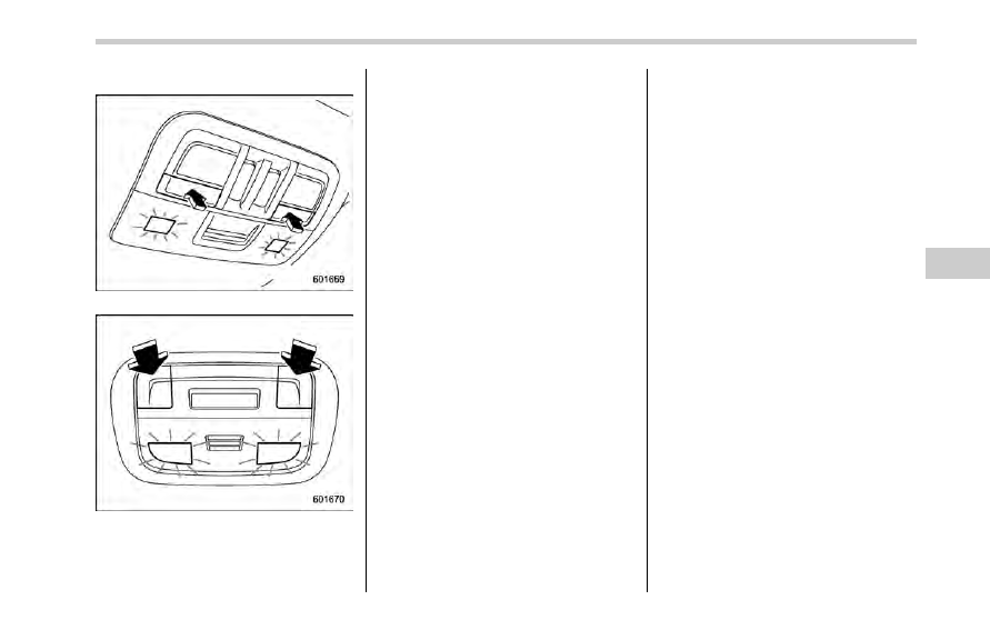
& Map lights
Type A
Type B
To turn on the map light, push the switch.
To turn it off, push the switch again.
NOTE
For the type A map lights, although the
light switches are in the ON position,
the lights are automatically turned off
after approximately 30 seconds of
illumination to prevent the 12 V aux-
iliary battery from discharging. For
details, refer to
“Battery drainage pre-
vention function
” F2-15.
! Automatic illumination (models
with moonroof)
The map lights illuminate automatically in
the following cases.
. Any of the doors other than the rear
gate is opened. (The map lights do not
illuminate when only the rear gate is
opened.)
. The doors are unlocked using the
keyless access function. Refer to
“Locking
and unlocking with
“keyless access” entry
function
” F2-6.
. The doors are unlocked using the
remote keyless entry system. Refer to
“Remote keyless entry system” F2-19.
. The ignition switch is turned from the
“ACC” position to the “OFF” position.
& OFF delay timer
The following lights have an automatic
illumination function.
. dome light
. map light (type A)
. cargo area light
After being illuminated automatically,
these lights remain on for several seconds
and then gradually turn off under the
following conditions.
. after all doors and the rear gate are
closed (dome light)
. after all doors are closed (type A map
light)
. after the rear gate is closed (cargo area
light)
While the lights are illuminated, if any of
the following operations are performed,
the lights turn off immediately.
. The ignition switch is turned from the
“OFF” position to the “ACC” or “ON”
position.
. All doors and the rear gate are locked
using the keyless access function.
. All doors and the rear gate are locked
using the remote keyless entry system.
The setting for the period of time in which
the lights remain on (OFF delay timer) can
be changed by a SUBARU dealer. Con-
Interior equipment/Interior lights
– CONTINUED –
6-3
Interior equipment/Sun visors
tact your SUBARU dealer for details. The
setting can be changed by operating the
multi function display. For details, refer to
“Interior light off delay timer setting” F3-
69.
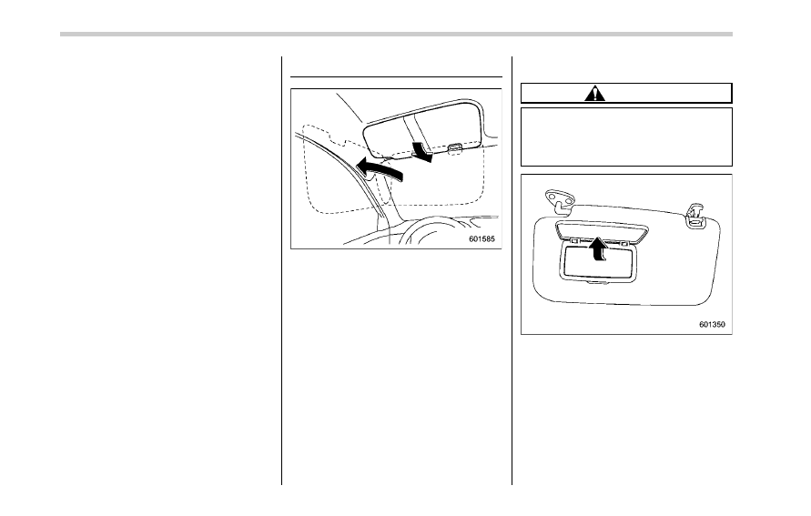
Sun visors
To block out glare, swing down the visors.
To use the sun visor at a side window,
swing it down and move it sideways.
& Vanity mirror
CAUTION
Keep the vanity mirror cover closed
while the car is being driven to avoid
being temporarily blinded by the
glare of bright light.
To use the vanity mirror, swing down the
sun visor and open the vanity mirror cover.
6-4
Storage compartment
CAUTION
. Always keep the storage com-
partment closed while driving to
reduce the risk of injury in the
event of a sudden stop or an
accident.
. Do not store spray cans, contain-
ers with flammable or corrosive
liquids or any other dangerous
items in the storage compart-
ment.
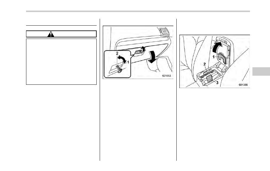
& Glove box
1)
Lock
2)
Unlock
To open the glove box, pull the handle. To
close it, push the lid firmly upward.
To lock the glove box, insert the mechan-
ical key and turn it clockwise. To unlock
the glove box, insert the mechanical key
and turn it counterclockwise.
NOTE
The mechanical key is directional. If the
key cannot be inserted, change the
direction that the grooved side is
facing and insert it again.
& Center console
The center console box provides a sto-
rage space.
1)
Paper holder
2)
Pen holder
3)
Card holder
The top of the console can be used as an
armrest.
Interior equipment/Storage compartment
– CONTINUED –
6-5
Interior equipment/Cup holders
For some models, the armrest is adjus-
table. Slide the armrest to the desired
position.
Cup holders
CAUTION
. Do not pick up a cup from the cup
holder or put a cup in the holder
while you are driving, as this may
distract you and lead to an
accident.
. Take care to avoid spills. Bev-
erages, if hot, might scald you
and/or your passengers. Spilled
beverages may also damage up-
holstery or carpets.
. When a cup in the rear passen-
ger
’s cup holder contains a bev-
erage, do not fold down the rear
seatback. Otherwise, the bever-
age could spill and, if the bev-
erage is hot, it could scald you
and/or your passengers.
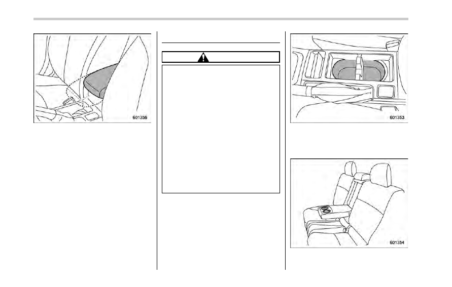
Front passenger
’s cup holder
A dual cup holder is built into the center
console.
Rear passenger
’s cup holder (if equipped)
A dual cup holder is built into the armrest.
6-6
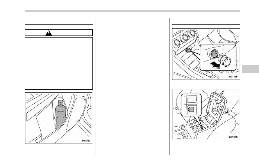
Bottle holders
CAUTION
. Do not pick up a bottle from the
bottle holder or put a bottle in the
holder while you are driving, as
this may distract you and lead to
an accident.
. When placing a beverage in a
bottle holder, make sure it is
capped. Otherwise, the beverage
could spill when opening/closing
the door or while driving and, if
the beverage is hot, it could scald
you and/or your passengers.
The bottle holder equipped on each door
trim can be used to hold beverage bottles
and other items.
Accessory power outlets
Power outlet below the climate control
dials
Power outlet in the center console
Accessory power outlets are provided
Interior equipment/Bottle holders
– CONTINUED –
6-7
Interior equipment/Accessory power outlets
below the climate control dials and in the
center console. Electrical power (12V DC)
from the battery is available at any of the
outlets when the ignition switch is in either
the
“ACC” or “ON” position.
You can use an in-vehicle electrical
appliance by connecting it to an outlet.
The maximum power rating of an appli-
ance that can be connected is 120W. Do
not use an appliance which exceeds the
indicated wattage for each outlet.
When using appliances connected to two
outlets simultaneously, the total power
consumed by them must not exceed
120W.
CAUTION
. Do not attempt to use a cigarette
lighter in the accessory power
outlets.
. Do not place any foreign objects,
especially metal ones such as
coins or aluminum foil, into the
accessory power outlet. That
could cause a short circuit. Al-
ways put the cap on the acces-
sory power outlet when it is not
in use.
. Use only electrical appliances
which are designed for 12V DC.
The maximum power rating of an
appliance that can be connected
is 120W. Do not use an appliance
which exceeds the indicated wat-
tage for each outlet.
When using appliances con-
nected to two outlets simulta-
neously, the total power con-
sumed by them must not exceed
120W. Overloading the accessory
power outlet can cause a short
circuit. Do not use double adap-
ters or more than one electrical
appliance.
. If the plug on your electric appli-
ance is either too loose or too
tight for the accessory power
outlet, this can result in a poor
contact or cause the plug to get
stuck. Only use plugs that fit
properly.
. Use of an electric appliance in the
accessory power outlet for a long
period of time while the engine is
not running can cause battery
discharge.
. Before driving your vehicle, make
sure that the plug and the cord
on your electrical appliance will
not interfere with your shifting
gears and operating the accel-
erator and brake pedals. If they
do, do not use the electrical
appliance while driving.
NOTE
When the lid of the center console is
closed, an opening remains between
the center console and the lid to allow
the power outlet in the center console
to be used. Pass the cord of the
electrical appliance through this open-
ing.
6-8
& Use with a cigarette lighter
(dealer option)
To use the accessory power outlet as a
cigarette lighter socket, purchase the
cigarette lighter plug, which is an optional
accessory. A cigarette lighter plug is
available from your SUBARU dealer.
The cigarette lighter operates only when
the ignition switch is in the
“ON” or “ACC”
position.
To use the cigarette lighter, push in the
knob and wait a few moments. It will
automatically spring up when ready for
use.
WARNING
To avoid being burned, never grasp
the lighter by the end with the
heating element. Doing so could
result in injury and could also
damage the heating element.
CAUTION
. Do not hold the lighter pushed in,
because it will overheat.
. The electrical power socket is
originally designed to use a gen-
uine SUBARU cigarette lighter
plug. Do not use a non-genuine
cigarette lighter plug in the sock-
et. Doing so may cause a short-
circuit and overheating, resulting
in a fire.
. If the socket is ever used for a
plug-in accessory such as a cell
phone, that may damage the
portion of the socket
’s internal
mechanism that causes a cigar-
ette lighter plug to
“pop out”
after its lighter element is heated.
Therefore, do not place a cigar-
ette lighter plug in a socket that
has been used, even once, to
power a plug-in accessory. Doing
so may cause the plug to stick
and overheat, creating a potential
fire hazard.
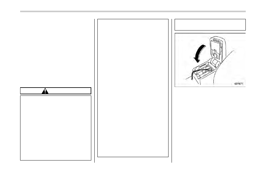
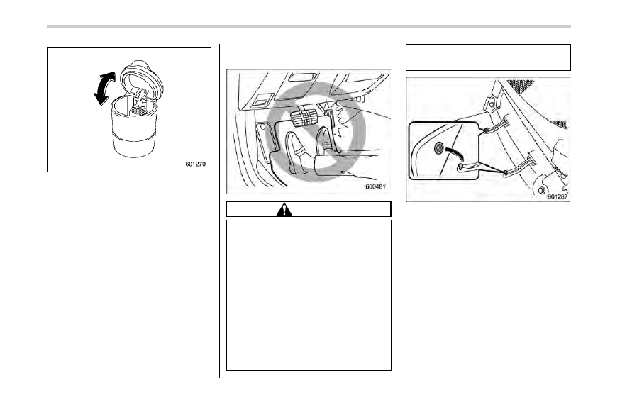
Ashtray (dealer option)
CAUTION
. Do not use ashtrays as waste
receptacles or leave a lighted
cigarette in an ashtray. This
could cause a fire.
. Always extinguish matches and
cigarettes before putting them
into the ashtray, and then close
the ashtray securely. If you keep
the ashtray open, the fire of the
cigarette may spread to another
cigarette butt and start a fire.
. Do not put flammable material in
the ashtray.
. Do not leave a lot of cigarette
butts in the ashtray.
NOTE
Particles of ash and tobacco will accu-
mulate around the hinges of the ash-
tray
’s inner lid. Clean them off using a
toothbrush or a similar narrow-ended
implement.
Interior equipment/Ashtray (dealer option)
– CONTINUED –
6-9
Interior equipment/Floor mat
The portable ashtray can be installed in
each cup holder or bottle holder. For the
locations of the cup holders, refer to
“Cup
holders
” F6-6. For the locations of the
bottle holders, refer to
“Bottle holders” F6-
7.
When using the ashtray, open the lid of the
ashtray. Fully close the lid after using the
ashtray to help reduce residual smoke.
Floor mat (if equipped)
CAUTION
If the floor mat slips forward and
interferes with the movement of the
pedals during driving, it could cause
an accident. Observe the following
precautions to prevent the floor mat
from slipping forward.
. Be sure to use a genuine
SUBARU floor mat or an equiva-
lent designed with grommets in
the correct locations.
. Make sure that the driver’s floor
mat is placed in its proper loca-
tion and is correctly secured on
its retaining pins.
. Do not use more than one floor
mat.
Retaining pins are located on the driver
’s
side floor.
The floor mat should be properly secured
using the built-in grommets, by placing the
grommets over the pins and pushing them
downward.
6-10
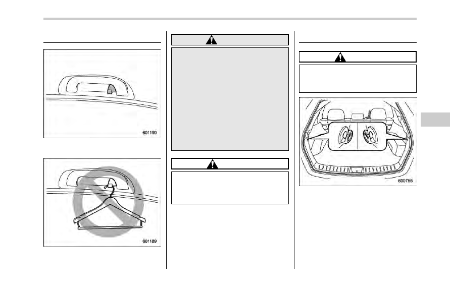
Coat hook
A coat hook is attached to the rear
passenger
’s hand grip.
WARNING
Hang clothing directly on the coat
hooks without using hangers. Do
not hang coat hangers or other hard
or pointed objects on the coat
hooks. If such items are hanging
on the coat hooks, when the SRS
curtain airbags deploy, they could
cause serious injuries by coming off
the coat hooks and being thrown
through the cabin or by preventing
correct airbag deployment. Before
hanging clothing on the coat hooks,
make sure there are no pointed
objects in the pockets.
CAUTION
Never hang anything on the coat
hook that might obstruct the driver
’s
view or that could cause injury in
sudden stops or in a collision.
Shopping bag hook
CAUTION
Do not hang items on the shopping
bag hook that weigh 6 lbs (3 kg) or
more.
A shopping bag hook is attached to each
side of the cargo area.
Interior equipment/Coat hook
6-11
Interior equipment/Cargo area cover
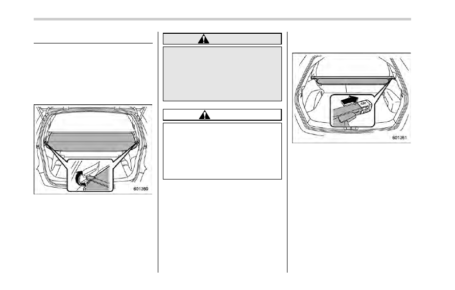
Cargo area cover
The cargo area cover is provided for
covering the cargo area and to protect its
contents from direct sunlight. This cover is
detachable to make room for additional
cargo.
& Using the cover
To extend the cover, pull the end of the
cover out of the housing, then insert its
hooks into the catches as shown. To
rewind it, unhook it from the catches and
it will rewind automatically. You should
hold on to the cover and guide it back into
the cover housing while it is rewinding.
WARNING
Do not place anything on the ex-
tended cover. Putting excessive
weight on the extended cover can
break it and an object on the cover
could tumble forward in the event of
a sudden stop or collision. This
could cause serious injury.
CAUTION
Be careful not to scratch the rear
gate stays while extending and
rewinding the cover.
Scratches on the stays could cause
leakage of gas from the stays, which
may result in their inability to hold
the rear gate open.
& To remove the cover housing
1. Rewind the cover.
2. Push the cover housing to the right
side and shorten it.
3. Take it off the retainer.
6-12
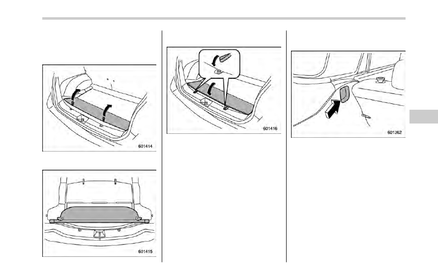
& Stowage of the cargo area
cover
The cargo area cover can be stowed in
under the cargo floor.
1. Raise and fold the rear end of the
cargo floor board.
2. Stow the cover housing in the cargo
area end.
3. Put the cargo floor board back while
hanging two retaining straps on the hooks
that are located on the rear wall of cargo
area.
& To install the cover housing
1. Shorten the cover housing.
2. Insert both ends of the cover housing
into the recesses of the retainers.
Interior equipment/Cargo area cover
6-13
Interior equipment/Cargo tie
–down hooks
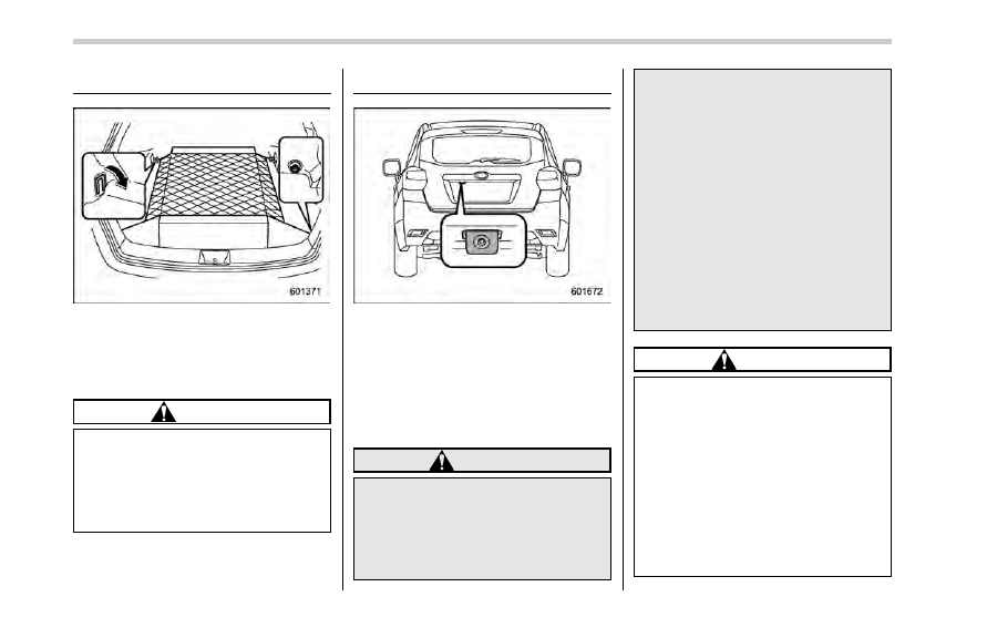
Cargo tie-down hooks
The cargo area is equipped with four tie-
down hooks so that cargo can be secured
with a cargo net or ropes.
When using the front tie-down hooks, turn
them down out of the storing recesses.
CAUTION
The cargo tie-down hooks are de-
signed only for securing light cargo.
Never try to secure cargo that
exceeds the capacity of the hooks.
The maximum load capacity is 22
lbs (10 kg) per hook.
Rear view camera
A rear view camera is attached to the rear
gate. When the ignition switch is
“ON” and
the select lever is set to
“R”, the rear view
camera automatically displays the rear
view image behind the vehicle on one of
the following displays.
. Navigation display (if equipped)
. Audio display (if equipped)
WARNING
. Since the rear view camera uses
a wide-angle lens, the image on
the monitor is different from the
actual view in terms of distance.
. Since the range of the image on
the monitor is limited, you should
always check the rear view and
the surrounding area with your
eyes and mirrors, and move
backward at a slow speed. Mov-
ing backward only by checking
the rear view image from the
camera could cause an accident.
. Do not disassemble or modify the
camera, switch or wiring. If
smoke comes out or you smell
a strange odor, stop using the
rear view camera immediately.
Contact your SUBARU dealer
for an inspection. Continued use
may result in accident, fire or
electric shock.
CAUTION
. If your vehicle is washed with a
high-pressure washer, do not
allow water to contact the camera
directly. Entry of water in the
camera lens may result in con-
densation, malfunction, fire or
electric shock.
. Since the camera is a precision
device, do not subject it to strong
impacts. Otherwise, malfunction,
fire or electric shock may occur.
. If mud or snow sticks to or is
6-14

frozen on the camera, you must
be very careful when removing it.
Otherwise, damage to the camera
may cause a fire or electric
shock. Pour water or lukewarm
water over the camera to remove
mud and ice, and wipe it with a
soft, dry cloth.
. Do not put a flame close to the
camera or wiring. Otherwise, da-
mage or fire may occur.
. When replacing the fuse, be sure
to use a fuse with the specified
rating. Use of a fuse with a
different rating may result in a
malfunction.
. If the rear view camera is used for
a long time while the engine is
not operated, the battery may
become completely discharged.
NOTE
. Do not wipe the camera with alcohol,
benzine or paint thinner. Otherwise,
discoloration may occur. To remove
contamination, wipe the camera with a
cloth moistened with a diluted neutral
detergent and then wipe it with a soft,
dry cloth.
. When waxing the vehicle, be careful
not to apply the wax to the camera. If it
comes in contact with the camera,
moisten a clean cloth with a diluted
neutral detergent to remove the wax.
. The camera lens has a hard coating
to help prevent scratches. However,
when washing the vehicle or cleaning
the camera lens, be careful not to
scratch the camera lens. Do not use a
washing brush directly on the camera
lens. The image quality of the rear view
camera may deteriorate.
. Strong light shined on the camera
lens may develop vertical lines around
the light source. This is not a malfunc-
tion.
. Under fluorescent light, the display
may flicker. However, this is not a
malfunction.
. The image of the rear view camera
may be slightly different from the
actual color of the objects.
& How to use the rear view
camera
When the select lever is set to
“R”, the rear
view camera automatically displays the
rear view image from the vehicle. When
the lever is set to other positions, the
image before setting to
“R” is displayed.
1. Set the ignition switch to
“ON”.
2. Set the select lever to
“R”.
NOTE
. For models with the genuine
SUBARU navigation system, while the
navigation system is activated, the
image of the rear view camera will not
be displayed. However, the image of
the rear view camera has priority over
other screen displays.
. The image of the rear view camera is
horizontally reversed as is the case
with the vehicle rear view mirror or the
side view mirror.
. It may be difficult to see the image of
the rear view camera in the following
cases. This is not a malfunction of the
camera.
– The vehicle is in a dark place (at
night, in a tunnel, etc.).
– The vehicle is in an extremely hot
or cold place.
– An object (such as raindrops,
Interior equipment/Rear view camera
– CONTINUED –
6-15
Interior equipment/Rear view camera
snow, dirt, etc.) that disturbs the
view of the rear view camera sticks
to the lens of the camera.
– Strong light shined directly on
the camera lens (occasionally, there
are vertical lines on the screen).
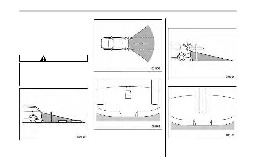
& Viewing range on the screen
CAUTION
The range that can be viewed with
the rear view camera is limited.
Always be sure to check with your
eyes when moving backward and
proceed slowly.
Range of view
Range of view
Image from camera
The area from the rear end of the bumper
can be viewed. Areas at both ends of the
bumper and areas just under the bumper
cannot be viewed.
Also, the image from the rear view camera
looks shorter than the actual distance.
Range of view
Image from camera
The area above the camera cannot be
viewed. If there is an object that has a
6-16
wide projection on its upper part such as a
sign pole behind the vehicle, the projec-
tion cannot be seen on the screen.
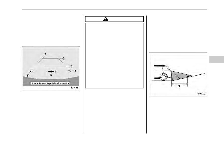
& Help line
The help line (distance marker and vehicle
width line) is a guide to help you realize
the actual distance from the screen image.
1)
Vehicle width line (oblique vertical line)
2)
Approx. 10 feet (3 m) from the bumper
(green horizontal line)
3)
Approx. 3 feet (1 m) from the bumper
(yellow horizontal line)
4)
Approx. 1.5 feet (0.5 m) from the bumper
(red horizontal line)
5)
Vehicle centerline
When the select lever is set to position
“R”, the monitor screen displays the help
lines together with the rear view image.
CAUTION
. When moving backward, always
check the back with your eyes
without relying on the help lines.
. The actual position may be dif-
ferent from the indication of the
help lines.
. Differences may occur due to
number of passengers or loaded
cargo.
. When the vehicle is on a slope or
when the vehicle is inclined
against the road, the indication
is different from the actual posi-
tion.
. Be sure to observe the displayed
warning message
“Check Sur-
roundings Before Backing Up
”.
NOTE
If you shift to the
“R” range shortly
after turning on the ignition switch, the
warning message
“Check Surround-
ings Before Backing Up
” may not be
displayed. Wait for several seconds or
more after turning on the ignition
switch before shifting to the
“R” range.
Then the warning message will be
displayed.
! Difference between screen image
and actual road
The distance markers show the distance
for a level road when the vehicle is not
loaded. It may be different from the actual
distance depending on the loading condi-
tions or road conditions.
! When there is an upward slope at
the back
1)
3 feet (1 m)
The distance on the screen looks farther
than the actual distance.
Interior equipment/Rear view camera
– CONTINUED –
6-17
Нет комментариевНе стесняйтесь поделиться с нами вашим ценным мнением.
Текст