Subaru Impreza WRX (2014 year). Manual — part 8
2-28
Keys and doors/Moonroof
&
Moonroof switches
!
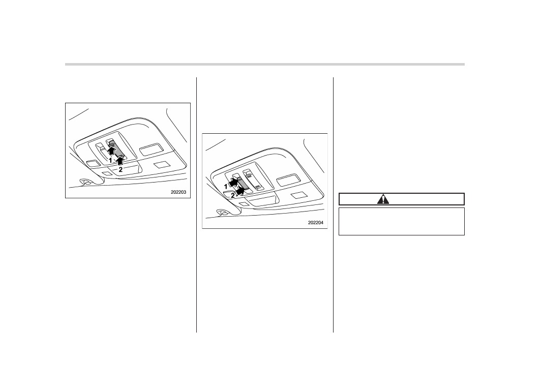
Tilting moonroof
1)
Raise
2)
Lower
The tilting function will only operate when
the moonroof is fully closed.
Push the rear side of the “UP/DOWN”
switch to raise the moonroof.
Push the front side of the “UP/DOWN”
switch to lower the moonroof.
Release the switch after the moonroof has
been raised or has been lowered com-
pletely. Pushing the switch continuously
may cause damage to the moonroof.
NOTE
One-touch operation does not take
place when the moonroof is lowered.
Push the switch continuously to raise
and lower the moonroof.
!
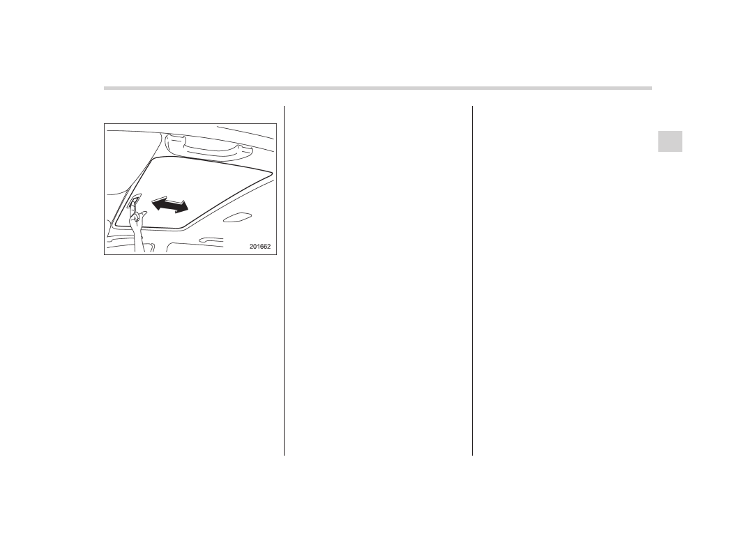
Sliding moonroof
1)
Open
2)
Close
Push the “OPEN/CLOSE” switch rearward
to open the moonroof. The sun shade will
also be opened together with the moon-
roof.
Push the “OPEN/CLOSE” switch forward
to close the moonroof.
To stop the moonroof at a selected mid-
way position while opening or closing it,
momentarily push the switch to the
“OPEN” side or “CLOSE” side.
After washing the vehicle or after it rains,
wipe away water on the roof prior to
opening the moonroof to prevent drops
of water from falling into the passenger
compartment.
!
Anti-entrapment function
When the moonroof senses a substantial
enough object trapped between its glass
and the vehicle’s roof during closure, it
automatically moves back to the fully open
position and stops there. The anti-entrap-
ment function may also be activated by a
strong shock on the moonroof even when
there is nothing trapped.
CAUTION
Never attempt to test this function
using fingers, hands or other parts
of your body.
NOTE
For the sake of safety, it is recom-
mended that you avoid driving with the
moonroof fully opened.
&
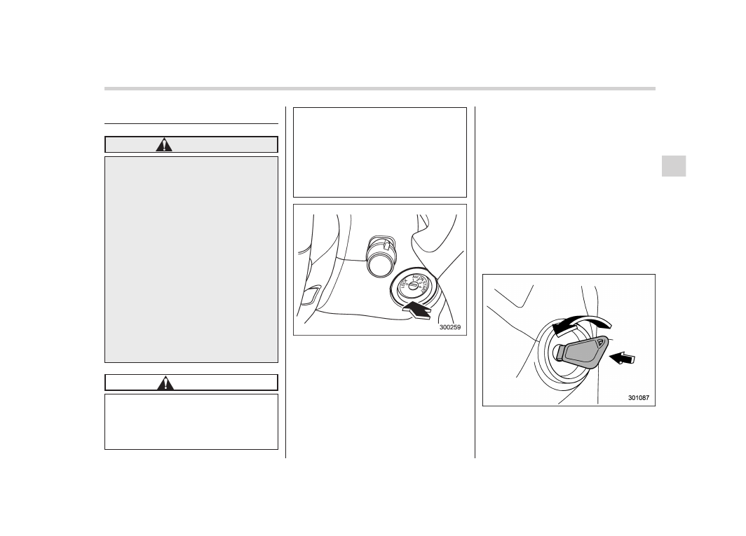
Sun shade
The sun shade can be slid forward or
backward by hand while the moonroof is
closed.
If the moonroof is opened, the sun shade
also moves back.
Keys and doors/Moonroof
2-29
— — — — — — — — — — — — — — — — — — — — — — — — — — — — — — — — — — — — — — — —
— — — — — — — — — — — — — — — — — — — — — — — — — — — — — — — — — — — — — — — —
— — — — — — — — — — — — — — — — — — — — — — — — — — — — — — — — — — — — — — — —
— — — — — — — — — — — — — — — — — — — — — — — — — — — — — — — — — — — — — — — —
— — — — — — — — — — — — — — — — — — — — — — — — — — — — — — — — — — — — — — — —
— — — — — — — — — — — — — — — — — — — — — — — — — — — — — — — — — — — — — — — —
— — — — — — — — — — — — — — — — — — — — — — — — — — — — — — — — — — — — — — — —
— — — — — — — — — — — — — — — — — — — — — — — — — — — — — — — — — — — — — — — —
— — — — — — — — — — — — — — — — — — — — — — — — — — — — — — — — — — — — — — — —
— — — — — — — — — — — — — — — — — — — — — — — — — — — — — — — — — — — — — — — —
— — — — — — — — — — — — — — — — — — — — — — — — — — — — — — — — — — — — — — — —
— — — — — — — — — — — — — — — — — — — — — — — — — — — — — — — — — — — — — — — —
— — — — — — — — — — — — — — — — — — — — — — — — — — — — — — — — — — — — — — — —

Ignition switch . . . . . . . . . . . . . .
3-3
LOCK. . . . . . . . . . . . . . . . ..
3-3
Acc. . . . . . . . . . . . . . . . . .
3-4
ON. . . . . . . . . . . . . . . . . ..
3-4
START . . . . . . . . . . . . . . . .
3-4
Key reminder chime . . . . . . . . . . .
3-4
Ignition switch light . . . . . . . . . . . .
3-4
Hazard warning flasher. . . . . . . . . ...
3-5
Meters and gauges. . . . . . . . . . . ..
3-5
Combination meter illumination . . . . . . ...
3-5
Canceling the function for meter/gauge needle
movement upon turning on the ignition
switch. . . . . . . . . . . . . . . ...
3-6
Meter/Gauge needle illumination setting (except
STI). . . . . . . . . . . . . . . . ...
3-6
Speedometer. . . . . . . . . . . . . ...
3-7
Odometer/Trip meter. . . . . . . . . . .
3-7
Tachometer . . . . . . . . . . . . . . .
3-9
Fuel gauge. . . . . . . . . . . . . . ..
3-9
Temperature gauge . . . . . . . . . . .
3-10
REV indicator light and buzzer (STI). . . . .
3-10
Setting the alarm-level engine speed. . . . ...
3-11
Deactivating the REV alarm system. . . . . .
3-12
Warning and indicator lights . . . . . . . .
3-12
Seatbelt warning light and chime . . . . . .
3-13
SRS airbag system warning light . . . . . .
3-14
Front passenger’s frontal airbag ON and OFF
indicators. . . . . . . . . . . . . . .
3-14
CHECK ENGINE warning light/Malfunction
indicator light. . . . . . . . . . . . ...
3-15
Charge warning light . . . . . . . . . . ..
3-16
Oil pressure warning light . . . . . . . . ..
3-16
Rear differential oil temperature warning light
(STI) . . . . . . . . . . . . . . . .
3-16
Low tire pressure warning light (U.S.-spec.
models) . . . . . . . . . . . . . . ...
3-16
ABS warning light. . . . . . . . . . . ..
3-18
Brake system warning light. . . . . . . .
3-19
Low fuel warning light . . . . . . . . . ...
3-20
Hill start assist warning light/Hill start assist OFF
indicator light (STI) . . . . . . . . . . ..
3-20
Door open warning light . . . . . . . . .
3-20
Vehicle Dynamics Control warning light/Vehicle
Dynamics Control operation indicator light . ...
3-20
Vehicle Dynamics Control OFF indicator light/
Traction Control OFF indicator light (STI). . ..
3-21
Security indicator light . . . . . . . . . ...
3-23
SI-DRIVE indicator light (STI). . . . . . . ..
3-23
Shift-up indicator light (STI) . . . . . . . ...
3-23
Turn signal indicator lights. . . . . . . . .
3-24
High beam indicator light . . . . . . . . ...
3-24
Cruise control indicator light. . . . . . . ..
3-24
Cruise control set indicator light . . . . . .
3-24
Front fog light indicator light (if equipped). . ..
3-24
Headlight indicator light . . . . . . . . . .
3-24
Driver’s control center differential auto indicator
light (STI) . . . . . . . . . . . . . .
3-24
Driver’s control center differential indicator and
warning lights (STI). . . . . . . . . . ..
3-25
REV indicator light (STI). . . . . . . . . .
3-25
Clock . . . . . . . . . . . . . . . . ..
3-26
Information display. . . . . . . . . . .
3-26
Outside temperature indicator . . . . . . .
3-27
Instruments and controls
3

Instruments and controls
Current fuel consumption (if equipped) . . . ...
3-28
Average fuel consumption . . . . . . . . ..
3-28
Turn off display of fuel consumption
indicator . . . . . . . . . . . . . . ..
3-28
Light control switch . . . . . . . . . . ...
3-29
Headlights. . . . . . . . . . . . . . ..
3-29
High/low beam change (dimmer) . . . . . . .
3-30
Headlight flasher . . . . . . . . . . . .
3-30
Daytime running light system . . . . . . . .
3-30
Turn signal lever . . . . . . . . . . . .
3-31
Illumination brightness control . . . . . . .
3-31
Headlight beam leveler (if equipped) . . . .
3-32
Front fog light switch (if equipped) . . . . ..
3-34
Wiper and washer. . . . . . . . . . . ..
3-34
Windshield wiper and washer switches . . . ..
3-36
Rear window wiper and washer switch –
5-door . . . . . . . . . . . . . . . .
3-37
Mirrors . . . . . . . . . . . . . . . .
3-38
Inside mirror. . . . . . . . . . . . . ..
3-38
Auto-dimming mirror/compass (if equipped) . ...
3-38
Auto-dimming mirror/compass with HomeLink
®
(if equipped) . . . . . . . . . . . . .
3-39
Outside mirrors . . . . . . . . . . . . .
3-45
Defogger and deicer . . . . . . . . . . ..
3-47
Tilt/telescopic steering wheel . . . . . . ...
3-48
Horn . . . . . . . . . . . . . . . . .
3-49
Ignition switch
WARNING
. Never turn the ignition switch to
“LOCK” while the vehicle is
being driven or towed because
that will lock the steering wheel,
preventing steering control. And
when the engine is turned off, it
takes a much greater effort than
usual to steer.
. Before leaving the vehicle, al-
ways remove the key from the
ignition switch for safety and
never allow an unattended child
to remain in the vehicle. Failure
to follow this procedure could
result in injury to a child or
others. Children could operate
the power windows, the moon-
roof or other controls or even
make the vehicle move.
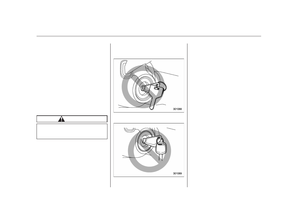
CAUTION
Do not attach a large key holder or
key case to either key. If it banged
against your knees or hands while
you are driving, it could turn the
ignition switch from the “ON” posi-
tion to the “Acc” or “LOCK” posi-
tion, thereby stopping the engine.
Also, if the key is attached to a
keyholder or to a large bunch of
other keys, centrifugal force may act
on it as the vehicle moves, resulting
in unwanted turning of the ignition
switch.
The ignition switch has four positions:
LOCK, Acc, ON and START.
NOTE
. Keep the ignition switch in the
“LOCK” position when the engine is
not running.
. Using electrical accessories for a
long time with the ignition switch in the
“ON” or “Acc” position can cause the
battery to go dead.
. If the ignition switch will not move
from the “LOCK” position to the “Acc”
position, turn the steering wheel
slightly to the left and right as you turn
the ignition switch.
&
LOCK
The key can only be inserted or removed
in this position. The ignition switch will lock
the steering wheel when you remove the
key.
If turning the key is difficult, turn the
steering wheel slightly to the right and left
as you turn the key.
The key can be turned from “Acc” to
“LOCK” only when the key is pushed in
while turning it.
Instruments and controls/Ignition switch
3-3
– CONTINUED –
3-4
Instruments and controls/Ignition switch
&
Acc
In this position the electrical accessories
(audio, accessory power outlet, etc.) can
be used.
&
ON
This is the normal operating position after
the engine is started.
&
START
The engine is started in this position. The
starter cranks the engine to start it. When
the key is released (after the engine has
started), the key automatically returns to
the “ON” position.
CAUTION
Do not turn the ignition switch to the
“START” position while the engine
is running.
If your registered key fails to start the
engine, pull out the key once (the security
indicator light will blink), and then insert
the key in the ignition switch and turn it to
the “START” position and again try to start
the engine.
NOTE
The engine may not start in the follow-
ing cases:
. The key grip is touching another key
or a metallic key holder.
. The key is near another key that
contains an immobilizer transponder.
. The key is near or touching another
transmitter.
&
Key reminder chime
The reminder chime sounds when the
driver’s door is opened and the ignition
switch is in the “LOCK” or “Acc” position.
The chime stops under the following
conditions.
. when the ignition switch is turned to the
“ON” position
. when the key is removed from the
ignition switch
. when the driver’s door is closed
&
Ignition switch light
For easy access to the ignition switch in
the dark, the ignition switch light illumi-
nates when the driver’s door is opened or
when the driver’s door is unlocked using
the remote keyless entry transmitter.
The light remains illuminated for several
tens of seconds and then gradually turns
off under the following conditions.
. when the driver’s door is closed
. when the doors are unlocked using the
remote keyless entry transmitter
The light turns off immediately under the
following conditions.
. when the ignition switch is turned to the
“ON” position
. when all doors and the rear gate (5-
door) are locked using the remote keyless
entry transmitter
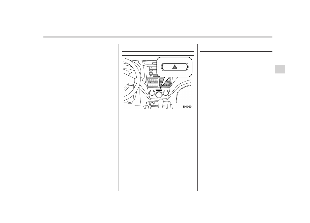
Hazard warning flasher
The hazard warning flasher is used to
warn other drivers when you have to park
your vehicle under emergency conditions.
The hazard warning flasher works regard-
less of the position of the ignition switch.
To turn on the hazard warning flasher,
push the hazard warning button on the
instrument panel. To turn off the flasher,
push the button again.
NOTE
When the hazard warning flasher is on,
the turn signals do not work.
Meters and gauges
NOTE
Liquid-crystal displays are used in
some of the meters and gauges on
the combination meter. You will find
their indications hard to see if you wear
polarized glasses.
&
Combination meter illumina-
tion
When the ignition switch is turned to the
“ON” position, the various parts of the
combination meter are illuminated in the
following sequence:
1. Warning lights, indicator lights, meter
needles and gauge needles illuminate.
2. Meter needles and gauge needles
each show MAX position.
3. Meter needles and gauge needles
each show MIN position.
4. Meter and gauge dials, odometer and
trip meter back light illuminate.
5. Regular illumination (for driving) be-
gins.
Instruments and controls/Hazard warning flasher
3-5
– CONTINUED –
3-6
Instruments and controls/Meters and gauges
&
Canceling the function for
meter/gauge needle move-
ment upon turning on the
ignition switch
It is possible to activate or deactivate the
movement of the meter needles and
gauge needles that takes place when the
ignition switch is turned to the “ON”
position.
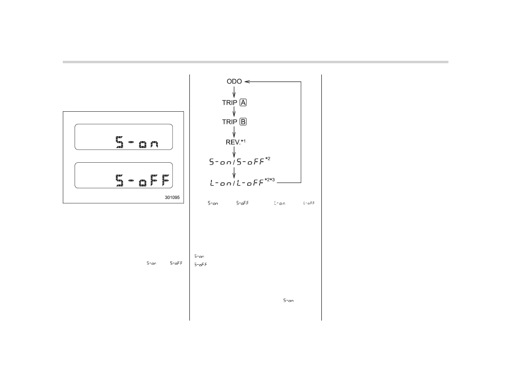
Turn the ignition switch to the “LOCK” or
“Acc” position.
Press the trip knob to show “
” or “
”
on the odometer and trip meter display.
The display can be switched as shown in
the following illustration by pressing the
trip knob.
*
1
: STI only
*
2
: “
” or “
”, and “
” or “
”
cannot be displayed when the ignition
switch is in the “ON” position.
*
3
: Except STI
To change the current setting, press the
trip knob for at least 2 seconds.
: Activated
: Deactivated
NOTE
. Your vehicle’s initial movement
setting of the meter/gauge needles
has been set for activation “
” at the
time of shipment from the factory.
. It is not possible to cancel the initial
movement setting of the meter/gauge
needles when the ignition switch is in
the “ON” position. Cancel the setting
when the ignition switch is in the
“LOCK” or “Acc” position.
&
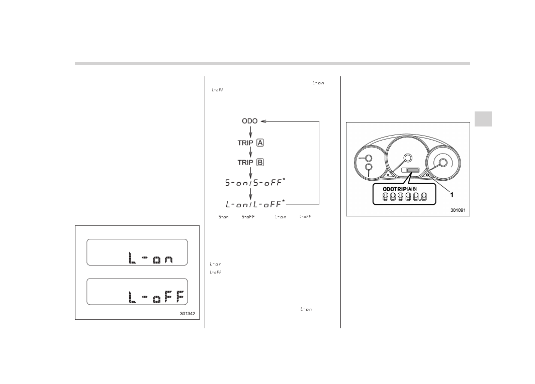
Meter/Gauge needle illumi-
nation setting (except STI)
When the setting is activated or deacti-
vated, the meter needles and gauge
needles illuminate and turn off as follows.
Activated:
When the driver’s door is opened while
the ignition switch is in the “LOCK”
position, the needles illuminate and turn
off after approximately 20 seconds. The
illumination of the needles gradually turns
off after the ignition switch is turned from
the “ON” position to the “LOCK” position.
Deactivated:
The needles do not illuminate when the
driver’s door is opened while the ignition
switch is in the “LOCK” position. The
illumination of the needles turns off im-
mediately after the ignition switch is turned
from the “ON” position to the “LOCK”
position.
NOTE
. Even during the illumination after
the driver’s door is opened, if the
ignition switch is turned to the “ON”
position, the combination meter will
illuminate as usual.
. If the doors are locked by the remote
keyless entry system during the illumi-
nation after the driver’s door is opened,
the illumination will be turned off.
. Even while the illumination gradu-
ally turns off after the ignition switch is
turned to the “LOCK” position, if the
ignition switch is turned to the “ON”
position, the combination meter illumi-
nate as usual.
To change the setting:
1. Turn the ignition switch to the “LOCK”
or “Acc” position.
2. Press the trip knob to show “
” or
“
” on the odometer and trip meter
display. The display can be switched as
shown in the following illustration by
pressing the trip knob.
*: “
” or “
”, and “
” or “
” cannot
be displayed when the ignition switch is
in the “ON” position.
3. To change the current setting, press
the trip knob for at least 2 seconds.
: Activated
: Deactivated
NOTE
The initial illumination setting of the
meter/gauge needles of your vehicle
has been set for activation “
” at the
time of shipment from the factory.
&
Speedometer
The speedometer shows the vehicle
speed.
&
Odometer/Trip meter
1)
Trip knob
This meter displays the odometer and two
trip meters when the ignition switch is in
the “LOCK”, “Acc” or “ON” position.
If you press the trip knob when the ignition
switch is in the “LOCK” position, the
odometer/trip meter will light up. It is
possible to switch the indications while
the odometer/trip meter is lit up. If you do
not press the trip knob within 10 seconds
of illumination of the odometer/trip meter,
the odometer/trip meter will turn off.
Instruments and controls/Meters and gauges
3-7
– CONTINUED –
3-8
Instruments and controls/Meters and gauges
The display can be switched as shown in
the following illustration by pressing the
trip knob.
*
1
: STI only
*
2
: “
” or “
”, and “
” or “
”
cannot be displayed when the ignition
switch is in the “ON” position.
*
3
: Except STI
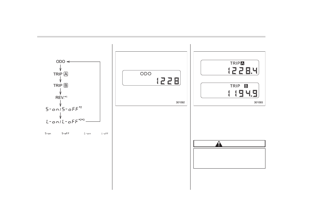
!
Odometer
The odometer shows the total distance
that the vehicle has been driven.
!
Double trip meter
The trip meter shows the distance that the
vehicle has been driven since you last set
it to zero.
To set the trip meter to zero, select the A
trip or B trip meter by pushing the knob
and keep the knob pushed for more than 2
seconds.
CAUTION
To ensure safety, do not attempt to
change the function of the indicator
during driving, as an accident could
result.
NOTE
If the connection between the combina-
tion meter and battery is broken for any
reason such as vehicle maintenance or
fuse replacement, the data recorded on
the trip meter will be lost.
&
Tachometer
The tachometer shows the engine speed
in thousands of revolutions per minute.
CAUTION
Do not operate the engine with the
pointer of the tachometer in the red
zone. This may cause severe da-
mage to the engine.
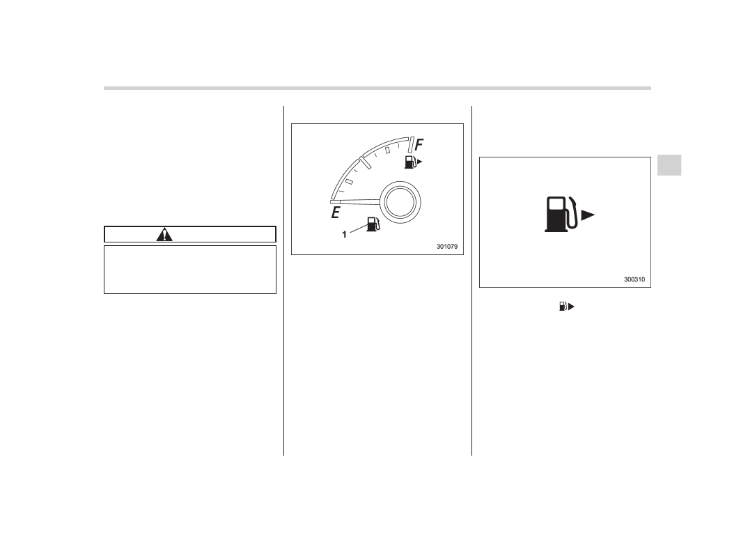
&
Fuel gauge
1)
Low fuel warning light (Refer to “Low fuel
The fuel gauge shows the approximate
amount of fuel remaining in the tank.
When the ignition switch is in the “LOCK”
or “Acc” position, the fuel gauge shows “E”
even if the fuel tank contains fuel.
The gauge may move slightly during
braking, turning or acceleration due to fuel
level movement in the tank.
If you press the trip knob while the ignition
switch is in the “LOCK” or “Acc” position,
the fuel gauge will light up and indicate the
amount of fuel remaining in the tank.
If, while the fuel gauge is indicating the
amount of fuel remaining in the tank, you
(a) do not press the trip knob for 10
seconds or (b) open and close the driver’s
door, the fuel gauge indication will turn off.
NOTE
You will see the “
” sign in the fuel
gauge meter.
This indicates that the fuel filler door
(lid) is located on the right side of the
vehicle.
Instruments and controls/Meters and gauges
3-9
– CONTINUED –
3-10
Instruments and controls/REV indicator light and buzzer (STI)
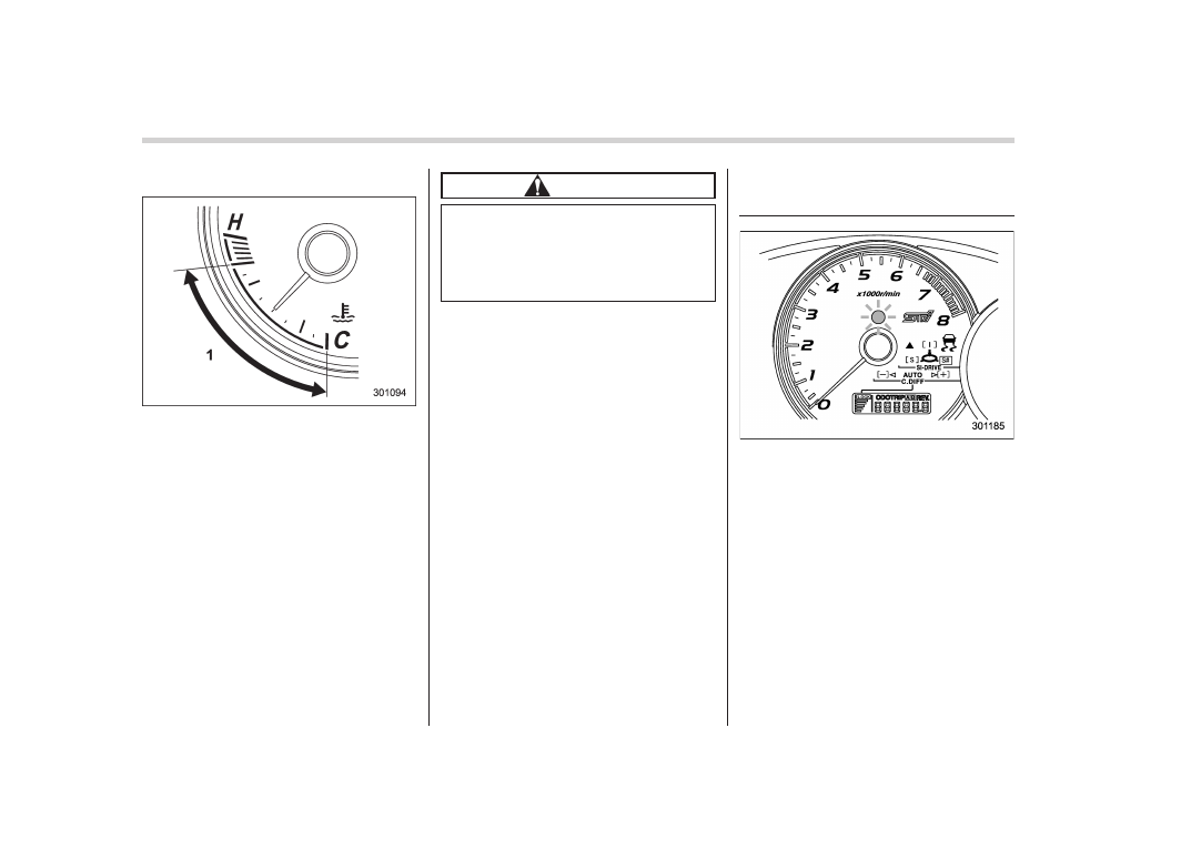
&
Temperature gauge
1)
Normal operating range
The temperature gauge shows engine
coolant temperature when the ignition
switch is in the “ON” position.
The coolant temperature will vary in
accordance with the outside temperature
and driving conditions.
We recommend that you drive moderately
until the pointer of the temperature gauge
reaches near the middle of the range.
Engine operation is optimum with the
engine coolant at this temperature range
and high revving operation when the
engine is not warmed up enough should
be avoided.
CAUTION
If the pointer exceeds the normal
operating range, safely stop the
vehicle as soon as possible.
Refer to “Engine overheating” F9-
12.
REV indicator light and buz-
zer (STI)
The REV alarm system has the following
functions.
. When the engine speed reaches the
level that was previously set, the REV
indicator light illuminates to inform you. At
this time, a buzzer also sounds if the
buzzer setting is activated.
. Whenever the engine speed enters the
red zone of the tachometer, the REV
indicator light flashes.
If you press the trip knob, the odometer/
trip meter will show the engine speed that
has already been set.

NOTE
Even if the REV alarm system is not set,
the REV indicator light will flash when-
ever the engine speed enters the red
zone of the tachometer.
&
Setting the alarm-level en-
gine speed
The alarm-level engine speed can be set
(in 100 rpm steps) within the range from
2,000 rpm to 7,000 rpm as follows.
1. Push the trip knob to select “REV” on
the combination meter.
2. When the trip knob is pushed for more
than 2 seconds, the thousands place
flashes.
3. Release your finger from the trip knob
once, then push and hold the trip knob
again. The number will change sequen-
tially from 2 to 7. Release your finger at
the desired alarm-level engine speed.
4. When the trip knob is pushed, the
hundreds place flashes.
5. Release your finger from trip knob
once, then push and hold the trip knob
again. The number will change sequen-
tially from 0 to 9. Release your finger at
the desired alarm-level engine speed.
6. When the trip knob is pushed, the
buzzer sounds and the REV alarm system
will automatically enter its new setting
mode (step 7 below), in which you can
activate or deactivate the buzzer.
7. Every time that the trip knob is pushed
and held, the buzzer changes to activate
or deactivate.
b – on: Activated
b – off: Deactivated
When the mode is changed to “activate”,
the buzzer sounds.
8. Push the trip knob to complete the
setting procedure.
NOTE
. The REV alarm system does not
operate while settings are being en-
tered.
. The speed-setting mode terminates
if “--00” rpm is selected.
. The speed-setting mode is canceled
if the ignition switch is turned from ON
Instruments and controls/REV indicator light and buzzer (STI)
3-11
– CONTINUED –
3-12
Instruments and controls/Warning and indicator lights
to OFF, OFF to ON, or the vehicle starts
moving before the setting procedure is
finished.
. Setting the speed is impossible
when the vehicle is moving.
. The set engine speed may differ
from the engine speed shown by the
tachometer. Use the engine speed
shown by the tachometer as a rough
guide.
. If the setting operation is performed
with the engine switch turned off, the
REV indicator light turns off and the
setting operation is aborted when you
have stopped the setting operation for
approximately 10 seconds.
. If the setting operation is performed
with the engine switch turned off, the
REV indicator light turns off and the
setting operation is aborted when you
open and close the driver’s door.
&
Deactivating the REV alarm
system
To deactivate the REV indicator light and
buzzer functions of the REV alarm system,
set the thousands place of the alarm-level
engine speed to “–”.
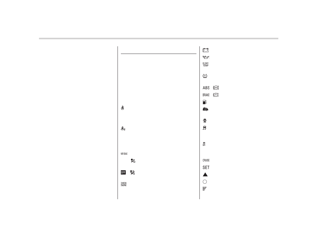
Warning and indicator lights
Several of the warning and indicator lights
illuminate momentarily and then turn off
when the ignition switch is initially turned
to the “ON” position. This permits check-
ing the operation of the bulbs.
Apply the parking brake and turn the
ignition switch to the “ON” position. For
the system check, the following lights
illuminate and turn off after several sec-
onds or after the engine has started:
: Seatbelt warning light
(The seatbelt warning light turns off
only when the driver fastens the
seatbelt.)
: Front passenger’s seatbelt warning
light
(The seatbelt warning light turns off
only when the front seat passenger
fastens the seatbelt.)
: SRS airbag system warning light
ON /
: Front passenger’s frontal airbag
ON indicator light
/
: Front passenger’s frontal airbag
OFF indicator light
: CHECK ENGINE warning light/Mal-
function indicator light
: Charge warning light
: Oil pressure warning light
: Rear differential oil temperature warn-
ing light (STI)
: Low tire pressure warning light
(U.S.- spec. models)
/
: ABS warning light
/
: Brake system warning light
: Low fuel warning light
: Hill start assist warning light/Hill start
assist OFF indicator light (STI)
: Door open warning light
: Vehicle Dynamics Control warning
light/Vehicle Dynamics Control opera-
tion indicator light
: Vehicle Dynamics Control OFF indica-
tor light/Traction Control OFF indicator
light (STI)
: Cruise control indicator light
: Cruise control set indicator light
: Shift-up indicator light (STI)
: REV indicator light (STI)
: Driver’s control center differential
indicator and warning lights (STI)
If any lights fail to illuminate, it indicates a
burned-out bulb or a malfunction of the
corresponding system.
Consult your authorized SUBARU dealer
for repair.
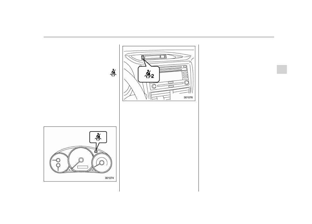
&
Seatbelt warning light
and chime
Your vehicle is equipped with a seatbelt
warning device at the driver’s and front
passenger’s seat, as required by current
safety standards.
With the ignition switch turned to the “ON”
position, this device reminds the driver
and front passenger to fasten their seat-
belts by illuminating the warning lights in
the locations indicated in the following
illustration and sounding a chime.
Driver’s warning light
Front passenger’s warning light
!
Operation
If the driver and/or front passenger have/
has not yet fastened the seatbelt(s) when
the ignition switch is turned to the “ON”
position, the seatbelt warning light(s) will
flash for 6 seconds, to warn that the
seatbelt(s) is/are unfastened. If the dri-
ver’s seatbelt is not fastened, a chime will
also sound simultaneously.
NOTE
. If the driver’s and/or front passen-
ger’s seatbelt(s) are/is still not fastened
6 seconds later, the seatbelt warning
device operates as follows according
to the vehicle speed.
– At speeds lower than approxi-
mately 9 mph (15 km/h)
The warning light(s) for unfastened
seatbelt(s) will alternate between
steady illumination and flashing at
15-second intervals. The chime will
not sound.
– At speeds higher than approxi-
mately 9 mph (15 km/h)
The warning light(s) for unfastened
seatbelt(s) will alternate between
flashing and steady illumination at
15-second intervals and the chime
will sound while the warning light(s)
is/are flashing.
. It is possible to cancel the warning
operation that follows the 6-second
warning after turning ON the ignition
switch. When the ignition switch is
turned ON next time, however, the
complete sequence of the warning
operation resumes. For further details
about canceling the warning operation,
please contact your SUBARU dealer.
If there is no passenger on the front
passenger’s seat, the seatbelt warning
device for the front passenger’s seat will
be deactivated. The front passenger’s
occupant detection system monitors
whether or not there is a passenger on
the front passenger’s seat.
Observe the following precautions. Failure
to do so may prevent the device from
functioning correctly or cause the device
Instruments and controls/Warning and indicator lights
3-13
– CONTINUED –
Нет комментариевНе стесняйтесь поделиться с нами вашим ценным мнением.
Текст