Subaru Tribeca (2014 year). Instruction — part 11
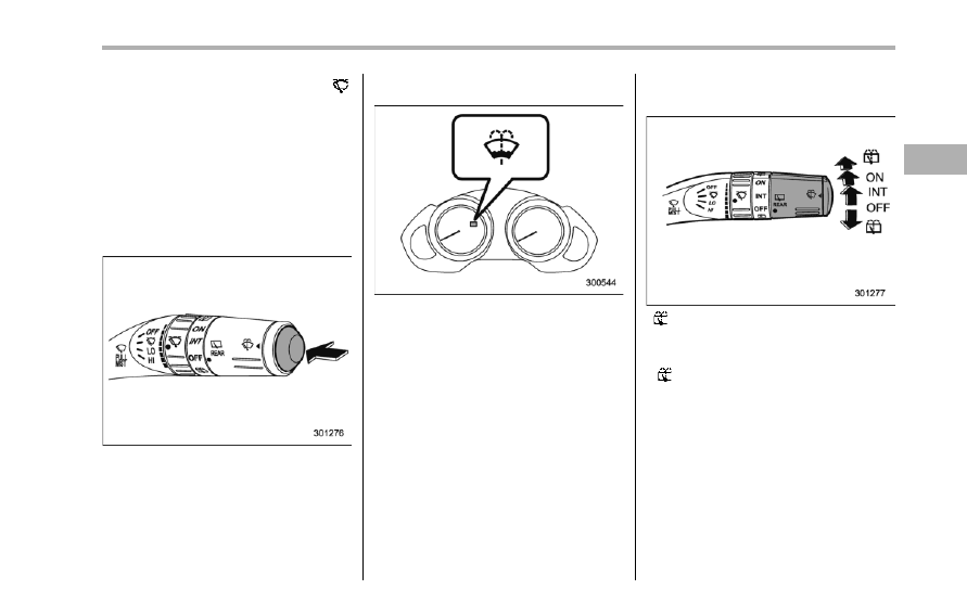
When the wiper switch is in the “ ”
position, turn the dial to adjust the operat-
ing interval of the wiper.
The operating interval can be adjusted in
nine steps.
The intermittent operation interval varies
depending on the vehicle speed in any of
the adjustment steps (longer when the
vehicle speed is low; shorter when the
vehicle speed is high).
! Washer
To wash the windshield, push the washer
button at the end of the wiper control lever.
The washer fluid sprays until you release
the washer button. The wipers operate
while you push the button.
NOTE
The windshield washer fluid warning
light illuminates when the washer fluid
level in the tank has dropped to the
lower limit. If the warning light illumi-
nates, refill the tank with fluid. For the
tank refilling method, refer to “Wind-
shield washer fluid” F11-28.
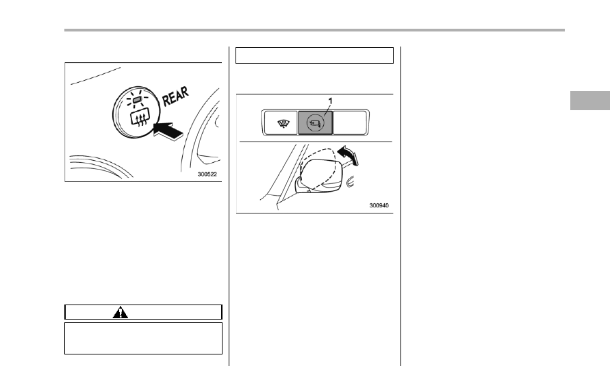
& Rear window wiper and
washer switch
: Washer (accompanied by wiper operation)
ON: Continuous
INT: Intermittent
OFF: Off
: Washer
! Rear wiper
To turn the rear wiper on, turn the knob on
the end of the wiper control lever upward
to the “INT” or “ON” position.
To turn the wiper off, return the knob on
the end of the lever to the “OFF” position.
With the switch turned to the “INT”
position, the rear wiper will operate inter-
mittently at intervals corresponding to the
vehicle speed (longer when the vehicle
Instruments and controls
3-35
– CONTINUED –
3-36
Instruments and controls
speed is low; shorter when the vehicle
speed is high).
When you subsequently move the select
lever of the automatic transmission to the
“R” position, the rear wiper will switch to
continuous operation. When you move the
select lever from the “R” position to some
other position, the rear wiper will return to
intermittent operation.
! Washer
To wash the rear window while the rear
wiper is operating, turn the knob on the
end of the wiper control lever upward to
the “ ” position. The washer fluid sprays
until you release the knob.
To wash the rear window when the rear
wiper is not in use, turn the knob on the
end of the wiper control lever downward to
the “ ” position. The washer fluid sprays
and the wiper operates until you release
the knob.
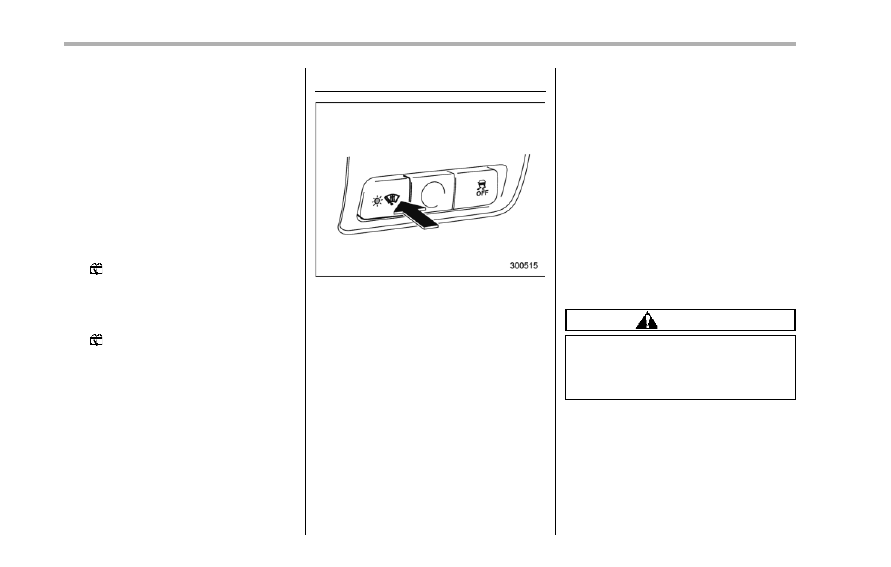
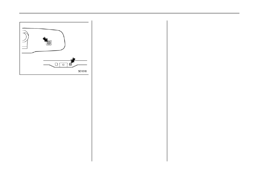
Windshield wiper deicer
The windshield wiper deicer operates only
when the ignition switch is in the “ON”
position.
To turn on the windshield wiper deicer,
push the control switch. The indicator light
located on the switch illuminates while the
windshield wiper deicer is operating.
To turn it off, push the control switch again.
It also turns off when the ignition switch is
turned to the “Acc” or “LOCK” position.
The windshield wiper deicer will automa-
tically shut off after approximately 15
minutes. If the windshield wiper blades
have been deiced completely before that
time, push the control switch to turn it off. If
deicing is not complete, you have to push
the control switch to turn it on again.
Your SUBARU dealer can set your wind-
shield wiper deicer to the continuous
operation mode. Contact your SUBARU
dealer for details.
Once the windshield wiper deicer has
been set to the continuous operation
mode, it should be in the continuous
operation mode at any time when the
control switch is pushed to the “ON”
position.
If the battery voltage drops below the
permissible level, continuous operation of
the windshield wiper deicer is canceled
and the system stops operating.
CAUTION
To prevent the battery from being
discharged, do not operate the
windshield wiper deicer continu-
ously for any longer than necessary.
NOTE
. Turn on the windshield wiper deicer
if the wipers are frozen to the wind-
shield.
. If the windshield is covered with
snow, remove the snow so that the
windshield wiper deicer works effec-
tively.
. While the windshield wiper deicer is
in the continuous operation mode, if
the vehicle speed remains at 9 mph (15
km/h) or less for 15 minutes, the wind-
shield wiper deicer automatically stops
operating.
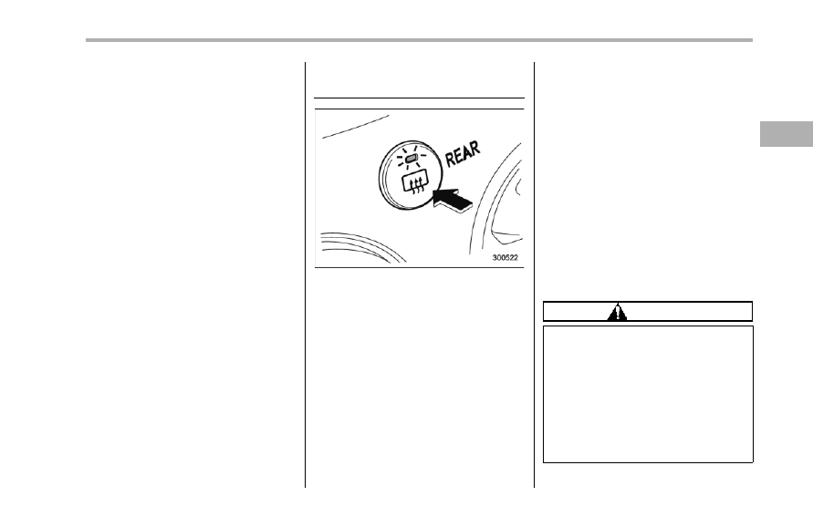
Rear window defogger but-
ton
The rear window defogger operates only
when the ignition switch is in the “ON”
position.
To turn on the defogger, push the control
switch that is located on the climate
control panel. The indicator light located
on the control switch illuminates while the
rear window defogger is operating.
To turn it off, push the control switch again.
It also turns off when the ignition switch is
turned to the “Acc” or “LOCK” position.
The defogger will automatically shut off
after approximately 15 minutes. If the rear
window has been cleared completely
before that time, push the control switch
to turn it off. If defrosting or defogging is
not complete, you have to push the control
switch to turn it on again.
Your SUBARU dealer can set your rear
window defogger to the continuous opera-
tion mode. Contact your SUBARU dealer
for details.
Once the rear window defogger has been
set to the continuous operation mode, it
should be in the continuous operation
mode at any time when the control switch
is pushed to the “ON” position.
If the battery voltage drops below the
permissible level, continuous operation of
the rear window defogger is canceled and
the system stops operating.
CAUTION
. Do not use sharp instruments or
window cleaner containing abra-
sives to clean the inner surface
of the rear window. They may
damage the conductors printed
on the window.
. To prevent the battery from being
discharged, do not operate the
defogger continuously for any
longer than necessary.
Instruments and controls
3-37
– CONTINUED –
3-38
Instruments and controls
NOTE
The outside mirror defogger also oper-
ates while the rear window defogger is
operating.
Mirrors
Always check that the inside and outside
mirrors are properly adjusted before you
start driving.
& Type A inside mirror (if
equipped)
The mirror has a day and night position.
Pull the tab at the bottom of the mirror
toward you for the night position. Push it
away for the day position. The night
position reduces glare from headlights.
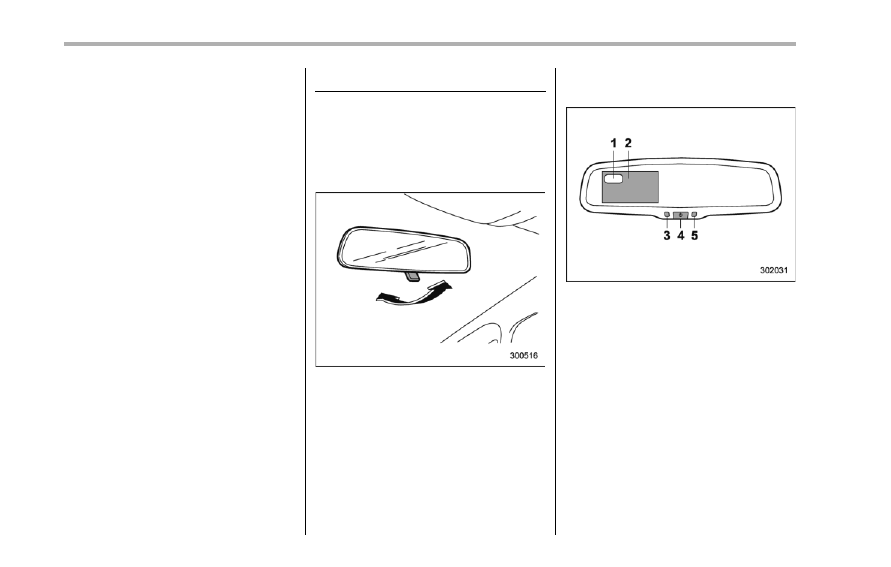
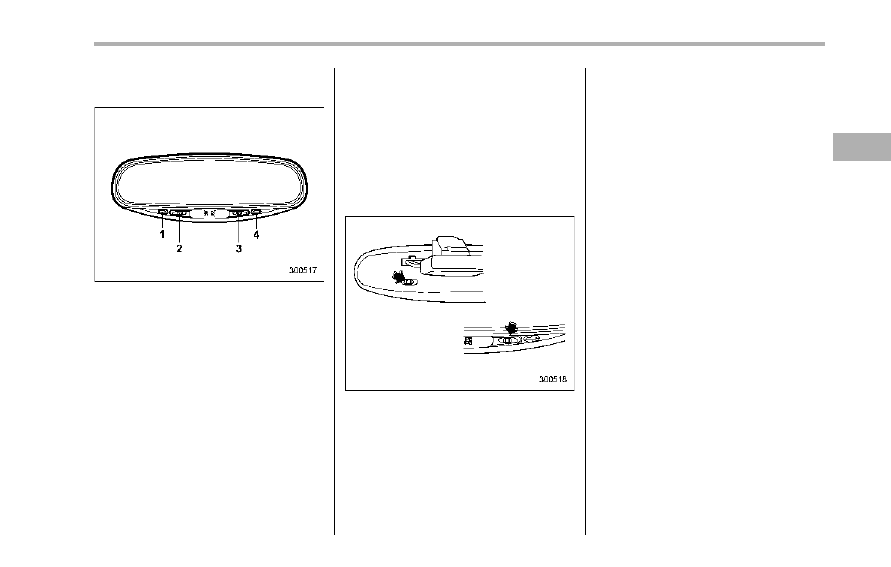
& Type B inside mirror (if
equipped)
1)
Electronic compass display
2)
Rear view image display
3)
Auto dimming indicator
4)
Multifunction button
5)
Photosensor
The mirror has the following features.
. Rear view image display
. Auto-dimming function for anti-glare
capability
. Electronic compass display
You can display the various functions of
these features based on how long you
press the multifunction button.
Gear
position
Period of
time multi-
function
button is
pressed
Function
displayed
R (reverse)
Briefly
Rear view display
ON/OFF*
More than
3 seconds
Help lines indica-
tion ON/OFF
Except
R (reverse)
Briefly
Auto-dimming
function ON/OFF*
3 to 6
seconds
Electronic com-
pass display ON/
OFF
6 to 9
seconds
Enter the com-
pass zone setting
mode
9 to 12
seconds
Enter the com-
pass calibration
mode
*: The setting returns to “ON” as a default
setting every time the ignition switch is turned to
the “ON” position.
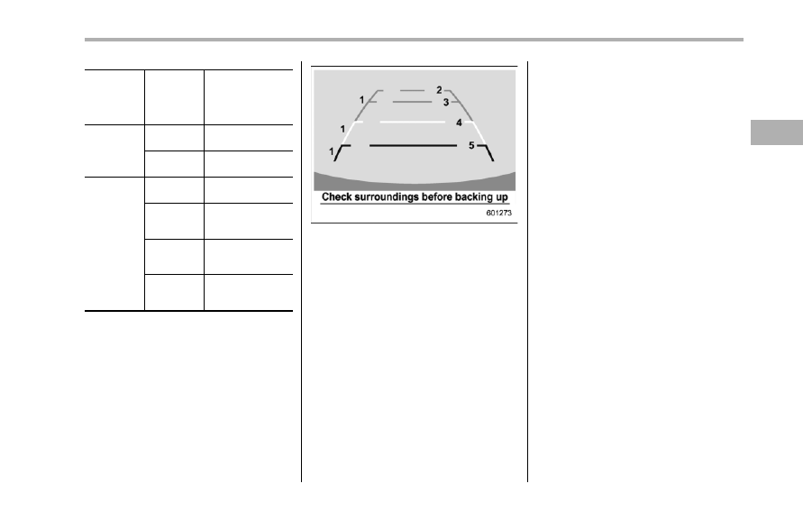
! Rear view image display
When the ignition switch is “ON” and the
select lever is set to “R”, the rear view
camera automatically displays the rear
view image behind the vehicle on the
inside mirror.
Also, the following help lines are indicated
as a guide to help you realize the actual
distance from the display.
1)
Vehicle width line (oblique vertical line)
2)
Approx. 10 feet (3 m) from the bumper
(green horizontal line)
3)
Approx. 6.5 feet (2 m) from the bumper
(green horizontal line)
4)
Approx. 3 feet (1 m) from the bumper
(yellow horizontal line)
5)
Approx. 1.5 feet (0.5 m) from the bumper
(red horizontal line)
These help lines are removable. To
remove the help lines, perform the follow-
ing procedure.
1. Display the rear view image on the
mirror.
2. Press the multifunction button for more
than 3 seconds to remove the help lines.
To display the help lines, press the multi-
function button for more than 3 seconds.
For precautions about the rear view
camera and the rear view image, refer to
“Rear view camera” F6-21.
! Auto-dimming function
The auto-dimming function is an anti-glare
capability which automatically reduces
glare coming from headlights of vehicles
behind you.
By briefly pressing the multifunction but-
ton, the auto-dimming function is toggled
on or off. When the auto-dimming function
is on, the auto dimming indicator light
(green) will illuminate.
Even with the mirror in anti-glare mode,
the mirror surface turns bright if the
transmission is shifted into reverse. This
is to ensure good rearward visibility during
reversing.
Instruments and controls
3-39
– CONTINUED –
3-40
Instruments and controls
The mirror has a photosensor attached on
both the front and back sides. Use care
not to cover the sensors with stickers, or
other similar items. Periodically wipe the
sensors clean using a piece of dry soft
cotton cloth or an applicator.
NOTE
When cleaning the mirror, use a paper
towel or similar item dampened with
glass cleaner. Do not spray glass
cleaner directly on the mirror surface.
By doing so, the sprayed glass cleaner
could enter the inside of the mirror
housing. That may cause a malfunction
in the mirror.
! Electronic compass display
By pressing the multifunction button for 3
to 6 seconds, the compass display is
toggled on or off. When the compass
display is on, an illuminated compass
reading will appear on the mirror.
Using the electronic compass properly,
the following compass zone adjustment
and compass calibration will be neces-
sary.
! Compass zone adjustment
1. The compass zone has been set to
zone “8” at the time of shipment from the
factory. Refer to the “Compass calibration
zones” map, which is attached to the end
of this instruction to verify that the compass
zone setting is correct for your geographi-
cal location.
2. Press and hold the multifunction but-
ton for 6 to 9 seconds, and then release it.
The zone number will be displayed.
3. Press the multifunction button repeat-
edly to cycle the display through all
possible zone settings. Stop cycling when
the correct zone number for your location
is displayed.
4. Releasing the button for 3 seconds will
exit the zone setting mode.
! Compass calibration
1. For optimum calibration, switch off all
nonessential electrical accessories (rear
window defogger, heater/air conditioning
system, spotlight, etc.) and ensure all
doors are shut.
2. Drive to an open, level area away from
large metallic objects or structures and
make certain the ignition switch is in the
“ON” position.
3. Press and hold the multifunction but-
ton for 9 to 12 seconds, and then release
it. The compass will enter the calibration
mode, then “C” and the direction will be
displayed.
4. Drive slowly in a circle until “C”
disappears from the display. Driving in
two or three circles might be necessary.
The compass is now calibrated.
5. Further calibration may be necessary
should outside influences cause the com-
pass to read inaccurately. You will notice
any outside influence if the compass tends
to read in only one particular direction.
Should you encounter this situation, return
to step 1 of the above procedure and
recalibrate the compass.
& Type C inside mirror (if
equipped)
1)
Left button
2)
Auto dimming indicator
3)
Photosensor
4)
Right button
This mirror has an anti-glare feature which
automatically reduces glare coming from
headlights of vehicles behind you. It also
contains a built-in compass.
. By pressing and releasing the left
button, the automatic dimming function is
toggled on or off. When the automatic
dimming function is on, the auto dimming
indicator light (green) located to the right
of the button will illuminate.
. By pressing and releasing the right
button, the compass display is toggled on
or off. When the compass is on, an
illuminated compass reading will appear
in the lower part of the mirror.
Even with the mirror in anti-glare mode,
the mirror surface turns bright if the
transmission is shifted into reverse. This
is to ensure good rearward visibility during
reversing.
! Photosensors
The mirror has a photosensor attached on
both the front and back sides. If the glare
from the headlights of vehicles behind you
strikes the mirror, these sensors detect it
and make the reflection surface of the
mirror dimmer to help prevent you from
being blinded. For this reason, use care
not to cover the sensors with stickers, or
other similar items. Periodically wipe the
sensors clean using a piece of dry soft
cotton cloth or an applicator.
! Compass calibration
1. For optimum calibration, switch off all
nonessential electrical accessories (rear
window defogger, heater/air conditioning
system, spotlight, etc.) and ensure all
doors are shut.
2. Drive to an open, level area away from
large metallic objects or structures and
make certain the ignition switch is in the
“ON” position.
3. Press and hold the left button for 3
seconds then release, and the compass
will enter the calibration mode. “CAL” and
direction will be displayed.
4. Drive slowly in a circle until “CAL”
disappears from the display (approxi-
mately two or three circles). The compass
is now calibrated.
5. Further calibration may be necessary
should outside influences cause the mirror
to read inaccurately. You will know that
this has occurred if your compass begins
to read in only limited directions. Should
you encounter this situation, return to step
one of the above procedure and recali-
brate the mirror.
Instruments and controls
3-41
– CONTINUED –
3-42
Instruments and controls
! Compass zone adjustment
1. The zone setting is factory preset to
Zone 8. Refer to the “Compass calibration
zone” map attached to the end of this
instruction to verify that the compass zone
setting is correct for your geographical
location.
2. Press and hold the right button for 3
seconds then release, and the word
“ZONE” will briefly appear and then the
zone number will be displayed.
3. Press the right-hand button repeatedly
to cycle the display through all possible
zone settings. Stop cycling when the
correct zone setting for your location is
displayed.
4. Releasing the button for 3 seconds will
exit the zone setting mode.
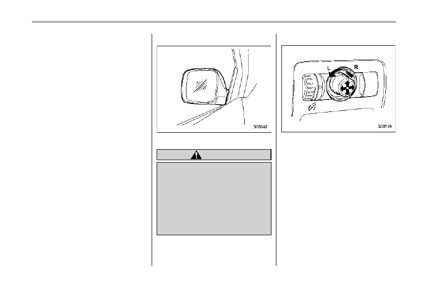
& Outside mirrors
! Convex mirror (passenger side)
WARNING
Objects look smaller in a convex
mirror and farther away than when
viewed in a flat mirror. Do not use
the convex mirror to judge the
distance of vehicles behind you
when changing lanes. Use the inside
mirror (or glance backwards) to
determine the actual size and dis-
tance of objects that you view in
convex mirror.
! Remote control mirror switch
The remote control mirrors operate only
when the ignition switch is in the “ON” or
“Acc” position.
1. Turn the knob to the “L” side to adjust
the left-hand mirror or to the “R” side to
adjust the right-hand mirror.
2. Move the knob in the direction you
want to move the mirror.
3. Return the knob to the neutral position
to prevent unintentional operation.
The mirrors can also be adjusted manu-
ally.
! Outside mirror defogger
The outside mirror defogger shares the
control switch with the rear window de-
fogger. Therefore, the outside mirror de-
fogger always operates with the rear
window defogger.
If the rear window defogger is set to the
continuous operation mode, the outside
mirror defogger also follows the contin-
uous setting.
For details, refer to “Rear window defog-
ger button” F3-37.
CAUTION
To prevent the battery from being
discharged, do not operate the de-
fogger continuously for any longer
than necessary.
! Power folding mirror switch (if
equipped)
1)
Power folding mirror switch
The power folding mirror switch operates
only when the ignition switch is in the “ON”
or “Acc” position.
To fold the outside mirrors, push the power
folding mirror switch. To unfold the mirrors,
push the switch again.
NOTE
. When the temperature is low, the
outside mirrors may stop during opera-
tion. Push the switch again. When the
outside mirrors do not work by switch
operation, move them several times
instructionly. This makes it possible to
operate them by switch operation.
. When you operate the power folding
mirror switch continuously, it may
temporarily stop working. This is not
a malfunction. Operate it again after
waiting for a short period of time.
. When you unfold the outside mirrors
instructionly, the mirrors may become
unstable. Be sure to unfold the mirrors
by switch operation. If the outside
mirrors are still unstable, fold the
mirrors again instructionly and then unfold
them by switch operation.
Instruments and controls
3-43
3-44
Instruments and controls
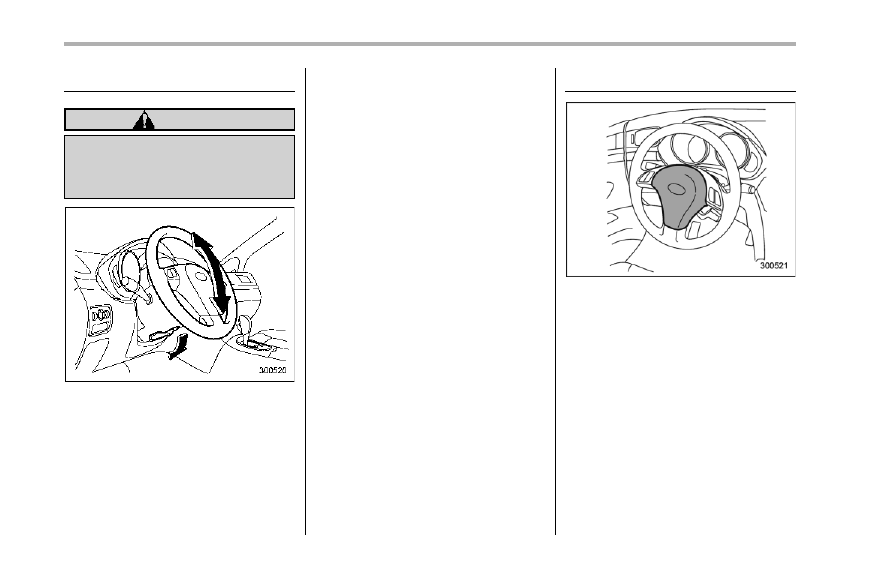
Tilt steering wheel
WARNING
Do not adjust the steering wheel tilt
position while driving. This may
cause loss of vehicle control and
result in personal injury.
1. Adjust the seat position. Refer to
“Front seats” F1-2.
2. Pull the tilt lock lever down.
3. Move the steering wheel to the desired
level.
4. Pull the lever up to lock the steering
wheel in place.
5. Make sure that the steering wheel is
securely locked by moving it up and down.
Horn
To sound the horn, push the horn pad.
Ventilator. . . . . . . . . . . . . . . ..
4-2
Airflow . . . . . . . . . . . . . . . .
4-2
Ventilator . . . . . . . . . . . . . . .
4-4
Automatic climate control system . . . . . .
4-5
Control panel . . . . . . . . . . . . . ..
4-5
Rear air conditioner. . . . . . . . . . . .
4-9
Temperature sensors. . . . . . . . . . ...
4-9
Operating tips for heater and air
conditioner. . . . . . . . . . . . . ... 4-10
Cleaning ventilator grille. . . . . . . . . . 4-10
Efficient cooling after parking in direct
sunlight . . . . . . . . . . . . . . ... 4-10
Lubrication oil circulation in the refrigerant
circuit. . . . . . . . . . . . . . . ..
4-10
Checking air conditioning system before summer
season . . . . . . . . . . . . . . .
4-10
Cooling and dehumidifying in high humidity and
low temperature weather conditions . . . . .
4-10
Air conditioner compressor shut-off when engine
is heavily loaded. . . . . . . . . . . ..
4-11
Refrigerant for your climate control system . .
4-11
Air filtration system . . . . . . . . . . ...
4-11
Replacing the air filter. . . . . . . . . .
4-11
Climate control
4
4-2
Climate control
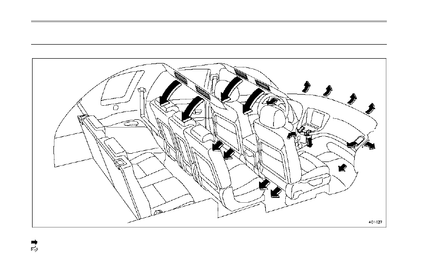
Ventilator
& Airflow
Ventilator and airflow
: Standard
: If equipped
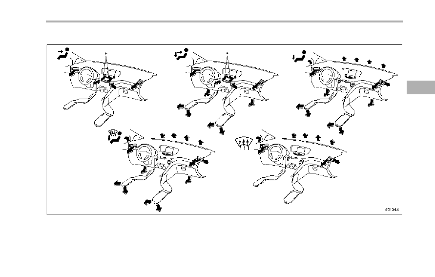
! Airflow mode selection
*: If equipped
Climate control
4-3
– CONTINUED –
4-4
Climate control
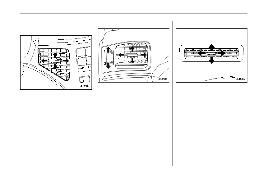
& Ventilator
! Center ventilators
Move the tab to adjust the flow direction.
! Side ventilators
1)
Open
2)
Close
Move the tab to adjust the flow direction.
To open the ventilator, turn the side grille
open/close wheel upward.
To close it, turn the wheel downward.
! Rear ventilators
Move the tab or rotate it to adjust the flow
direction.
Automatic climate control
system
NOTE
. Operate the automatic climate con-
trol system when the engine is running.
. The blower fan rotates at a low
speed when the engine coolant tem-
perature is low.
For efficient defogging or dehumidify-
ing in cold weather, press the “A/C”
button.
. The vehicle has a rear air condi-
tioner. The fan speed of the rear air
conditioner can be adjusted, but other
adjustments (outlet air temperature, air
distribution, etc.) are not possible for
the rear air conditioner. For details,
refer to “Rear air conditioner” F4-9.
The automatic climate control system
automatically controls outlet air tempera-
ture, fan speed, airflow distribution, air
inlet control, and air conditioner compres-
sor operation. It activates when the
“AUTO” button is pressed, and is used to
maintain a constant, comfortable climate
within the passenger compartment.
The temperature can be set within a range
of 65 to 858F (18 to 328C).
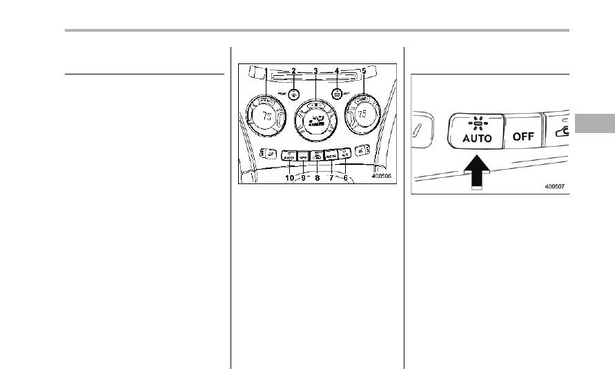
& Control panel
1)
Temperature control dial (driver’s side)
2)
Defroster button
3)
Fan speed control dial
4)
Rear window defogger button (Refer to
“Rear window defogger button” F3-37.)
5)
Temperature control dial (passenger’s
side)
6)
Air conditioner button
7)
Airflow mode selection button
8)
Air inlet selection button
9)
OFF button
10) AUTO button
! AUTO button
AUTO mode operation:
When the “AUTO” button is pressed, the
indicator light on the button illuminates. In
this state, fan speed, airflow distribution,
air inlet control, and air conditioner com-
pressor operation are automatically con-
trolled.
Manual mode operation:
If you operate any of the buttons on the
control panel other than the “OFF” button
and temperature control dial during auto-
matic mode operation, the indicator light
will turn off. You can then manually control
the system as desired using the button
you operated.
To change the system back to the AUTO
mode, press the “AUTO” button.
Climate control
4-5
– CONTINUED –
4-6
Climate control
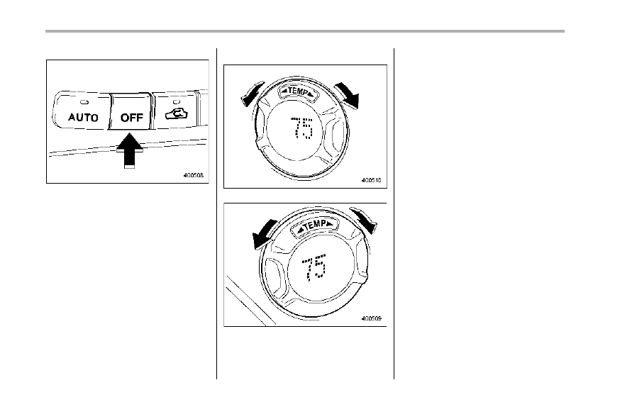
! OFF button
The Automatic Climate Control system
turns off (the air conditioner compressor
and fan turn off) when the “OFF” button is
pressed.
When the “OFF” button is pressed, the
outside air introduction mode (air inlet
selection OFF) is automatically selected.
! Temperature control dial
Driver’s side
Passenger’s side
It is possible to make separate tempera-
ture settings for the driver’s side and
passenger’s side. Each temperature
setting is shown on the display. With the
dial set at your desired temperature, the
system automatically adjusts the tempera-
ture of air supplied from the outlets such
that the desired temperature is achieved
and maintained.
Turning the dial counterclockwise and
releasing it reduces the temperature by
18F (0.58C). Turning the dial clockwise
and releasing it increases the temperature
by 18F (0.58C). Holding the dial in either
turned position causes the temperature to
change continuously.
With the minimum temperature set, the
system gives maximum cooling perfor-
mance. With the maximum temperature
set, the system gives maximum heating
performance.
Нет комментариевНе стесняйтесь поделиться с нами вашим ценным мнением.
Текст