Subaru XV Crosstrek Hybrid (2016 year). Instruction — part 9
Keys and doors/Rear gate
Rear gate
& Lock/unlock
The rear gate can be locked and unlocked
using any of the following systems.
. Power door locking switch: Refer to
“Power door locking switches” F2-16.
. Keyless access with the push-button
start system: Refer to
“Keyless access
with push-button start system
” F2-2.
. Remote keyless entry system: Refer to
“Remote keyless entry system” F2-19.
NOTE
If the rear gate cannot be unlocked due
to a discharged 12 V auxiliary battery, a
malfunction in the door locking/unlock-
ing system or other causes, you can
unlock it by instructionly operating the
rear gate lock release lever.
For the procedure, refer to
“Rear gate –
if the rear gate cannot be opened
” F9-
22.
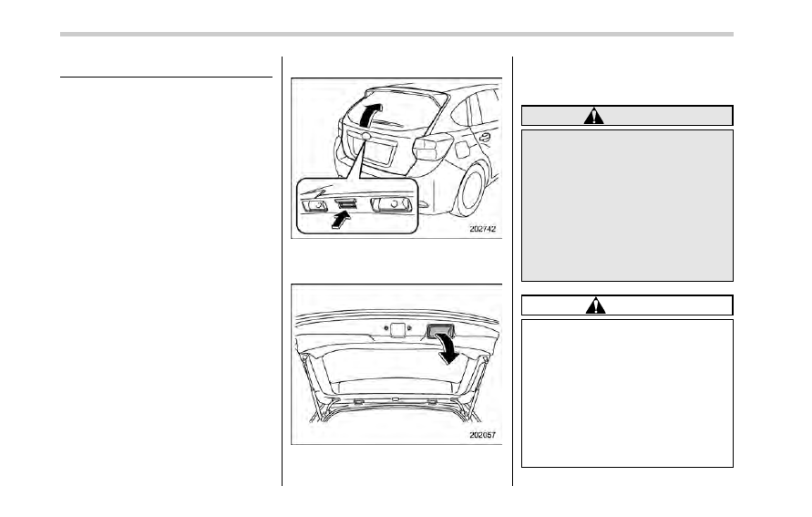
& Open/close
To open:
First unlock the rear gate lock then push
the rear gate opener button.
To close:
Lower the rear gate slowly and push down
firmly until the latch engages.
The rear gate can be lowered easily if you
pull it down holding the recessed grip.
WARNING
. To prevent dangerous exhaust
gas from entering the vehicle,
always keep the rear gate closed
while driving.
. Do not attempt to shut the rear
gate while holding the recessed
grip. Also avoid closing the rear
gate by pulling on the recessed
grip from inside the cargo space.
There is a danger of your hand
being caught and injured.
CAUTION
. Do not jam a plastic bag in or
place cellophane tape on the rear
gate stays or scratch the stays
while loading or unloading cargo.
That could cause leakage of gas
from the stays, which may result
in their inability to hold the rear
gate open.
. Be careful not to hit your head or
face on the rear gate when open-
ing or closing the rear gate and
2-30
when loading or unloading car-
go.
NOTE
If the rear gate cannot be unlocked due
to a discharged 12 V auxiliary battery, a
malfunction in the door locking/unlock-
ing system or other causes, you can
unlock it by instructionly operating the
rear gate lock release lever.
For the procedure, refer to
“Rear gate –
if the rear gate cannot be opened
” F9-
22.
Moonroof (if equipped)
WARNING
Never let anyone
’s hands, arms,
head or any objects protrude from
the moonroof. A person could be
seriously injured if any of the follow-
ing conditions occur.
. The vehicle stops suddenly.
. The vehicle turns sharply.
. The vehicle is involved in an
accident.
. Body parts protruding from the
vehicle are struck by outside
objects.
To avoid serious personal injury
caused by entrapment, always con-
form to the following instructions
without exception.
. Before closing the moonroof,
make sure that no one
’s hands,
arms, head or other objects will
be accidentally caught in the
moonroof.
. Always carry the key when you
leave the vehicle for safety rea-
sons and never allow an unat-
tended child to remain in the
vehicle. Failure to follow this
procedure could result in injury
to a child operating the moon-
roof.
. Never try to check the anti-en-
trapment function by deliberately
placing part of your body in the
moonroof.
CAUTION
. Do not sit on the edge of the open
moonroof.
. Do not operate the moonroof if
falling snow or extremely cold
conditions have caused it to
freeze shut.
. The anti-entrapment function
does not operate when the moon-
roof is being tilted down. Be sure
to confirm that it is safe to do so
before tilting the moonroof down.
. If the moonroof does not close,
we recommend that you have the
system checked by a SUBARU
dealer.
The moonroof has both tilting and sliding
functions.
The moonroof operates only when the
Keys and doors/Moonroof
– CONTINUED –
2-31
Keys and doors/Moonroof
ignition switch is in the
“ON” position.
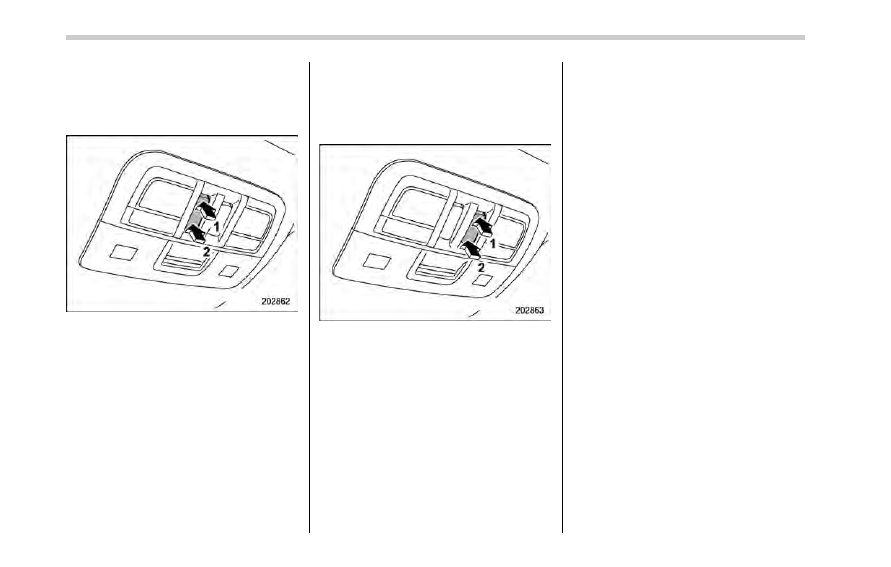
& Moonroof switches
! Tilting moonroof
1)
Raise
2)
Lower
The tilting function is activated only when
the moonroof is fully closed.
To raise:
Press the rear side of the
“UP/DOWN”
switch momentarily. The moonroof raises
completely.
To lower:
Press and hold the front side of the
“UP/
DOWN
” switch until the preferred position
has reached.
Release the switch after the moonroof has
been raised or has been lowered com-
pletely. Pressing the switch continuously
may cause damage to the moonroof.
! Sliding moonroof
1)
Open
2)
Close
To open:
Press and hold the rear side of the
“OPEN/CLOSE” switch. The sun shade
will also be opened together with the
moonroof. The moonroof will stop at a
position approximately 1.6 in (4 cm) away
from the fully opened position. Press and
hold the rear side of the switch again to
open the moonroof completely.
To close:
Press and hold the front side of the
“OPEN/CLOSE” switch.
To stop the moonroof at a selected mid-
way position while opening or closing it,
momentarily push the switch to the
“OPEN” side or “CLOSE” side.
After washing the vehicle or after it rains,
wipe away water on the roof prior to
opening the moonroof to prevent drops
of water from falling into the passenger
compartment.
NOTE
Driving with the moonroof fully open
can cause an annoying sound to be
generated at high speeds. If this oc-
curs, use the moonroof at the initial
stop position of 1.6 in (4 cm) away from
the fully opened position.
! Anti-entrapment function
When the moonroof senses a substantial
enough object trapped between its glass
and the vehicle
’s roof during closure, it
automatically moves back to the fully open
position and stops there. The anti-entrap-
ment function may also be activated by a
strong shock on the moonroof even when
there is nothing trapped.
2-32
CAUTION
Never attempt to test this function
using fingers, hands or other parts
of your body.
NOTE
For the sake of safety, it is recom-
mended that you avoid driving with the
moonroof fully opened.
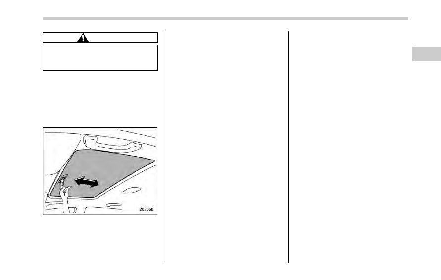
& Sun shade
The sun shade can be slid forward or
backward by hand while the moonroof is
closed.
If the moonroof is opened, the sun shade
also moves back.
Keys and doors/Moonroof
2-33
— — — — — — — — — — — — — — — — — — — — — — — — — — — — — — — — — — — — — — — —
— — — — — — — — — — — — — — — — — — — — — — — — — — — — — — — — — — — — — — — —
— — — — — — — — — — — — — — — — — — — — — — — — — — — — — — — — — — — — — — — —
— — — — — — — — — — — — — — — — — — — — — — — — — — — — — — — — — — — — — — — —
— — — — — — — — — — — — — — — — — — — — — — — — — — — — — — — — — — — — — — — —
— — — — — — — — — — — — — — — — — — — — — — — — — — — — — — — — — — — — — — — —
— — — — — — — — — — — — — — — — — — — — — — — — — — — — — — — — — — — — — — — —
— — — — — — — — — — — — — — — — — — — — — — — — — — — — — — — — — — — — — — — —
— — — — — — — — — — — — — — — — — — — — — — — — — — — — — — — — — — — — — — — —
— — — — — — — — — — — — — — — — — — — — — — — — — — — — — — — — — — — — — — — —
— — — — — — — — — — — — — — — — — — — — — — — — — — — — — — — — — — — — — — — —
— — — — — — — — — — — — — — — — — — — — — — — — — — — — — — — — — — — — — — — —
— — — — — — — — — — — — — — — — — — — — — — — — — — — — — — — — — — — — — — — —

Push-button ignition switch . . . . . . . ...
3-3
Safety precautions . . . . . . . . . . . ..
3-3
Operating range for push-button start system . ..
3-3
Switching power status . . . . . . . . . ...
3-3
When access key does not operate properly . .
3-4
Hazard warning flasher. . . . . . . . . ...
3-5
Meters and gauges. . . . . . . . . . . ..
3-5
Combination meter illumination . . . . . . ...
3-5
Canceling the function for meter/gauge needle
movement upon turning on the ignition
switch. . . . . . . . . . . . . . . ...
3-5
Meter/Gauge needle illumination setting. . . ...
3-6
Speedometer. . . . . . . . . . . . . ...
3-7
Odometer. . . . . . . . . . . . . . .
3-7
Double trip meter . . . . . . . . . . . .
3-8
Tachometer . . . . . . . . . . . . . . .
3-8
Fuel gauge . . . . . . . . . . . . . . ..
3-9
ECO gauge (if equipped) . . . . . . . . . .
3-9
Warning and indicator lights . . . . . . . .
3-10
Initial illumination for system check . . . . .
3-10
Seatbelt warning light and chime . . . . . .
3-11
SRS airbag system warning light . . . . . .
3-12
Front passenger
’s frontal airbag ON and OFF
indicators. . . . . . . . . . . . . . .
3-13
CHECK ENGINE warning light/Malfunction
indicator light. . . . . . . . . . . . ...
3-13
Coolant temperature low indicator light/Coolant
temperature high warning light . . . . . . .
3-14
Charge warning light . . . . . . . . . . ..
3-15
Oil pressure warning light . . . . . . . . ..
3-15
Engine low oil level warning light . . . . . ...
3-15
Windshield washer fluid warning light . . . .
3-16
AT OIL TEMP warning light. . . . . . . . .
3-16
Low tire pressure warning light (U.S.-spec.
models) . . . . . . . . . . . . . . ...
3-16
ABS warning light. . . . . . . . . . . ..
3-17
Brake system warning light (red). . . . . .
3-18
Low fuel warning light . . . . . . . . . ...
3-19
Hill start assist warning light/Hill start assist OFF
indicator light . . . . . . . . . . . . ..
3-20
Door open warning light . . . . . . . . .
3-20
All-Wheel Drive warning light . . . . . . . .
3-20
Power steering warning light. . . . . . . ..
3-20
Vehicle Dynamics Control warning light/Vehicle
Dynamics Control operation indicator light . ...
3-21
Vehicle Dynamics Control OFF indicator light . .
3-22
Warning chimes and warning indicator of the
keyless access with push-button start
system . . . . . . . . . . . . . . .
3-22
Security indicator light . . . . . . . . . ...
3-27
Select lever/gear position indicator. . . . . .
3-27
Turn signal indicator lights. . . . . . . . .
3-28
High beam indicator light . . . . . . . . ...
3-28
Cruise control indicator light. . . . . . . ..
3-28
Cruise control set indicator light . . . . . .
3-28
Automatic headlight beam leveler warning light
(models with HID headlights). . . . . . .
3-28
Front fog light indicator light (if equipped). . ..
3-28
Headlight indicator light (if equipped) . . . . .
3-28
BSD/RCTA warning indicator (if equipped) . . ..
3-28
BSD/RCTA OFF indicator (if equipped). . . .
3-28
Hybrid Fail Lamp . . . . . . . . . . . ...
3-28
Pedestrian alert warning light. . . . . . . .
3-29
Instruments and controls
3
Instruments and controls
Hybrid READY Indicator Light. . . . . . . .
3-29
EV (Electric Vehicle) mode lamp . . . . . . .
3-29
Multi function display . . . . . . . . . .
3-30
Safety precautions . . . . . . . . . . . .
3-30
Features . . . . . . . . . . . . . . .
3-30
Locations. . . . . . . . . . . . . . ...
3-31
Basic operation . . . . . . . . . . . . ..
3-31
Welcome screen. . . . . . . . . . . . .
3-31
Date screen. . . . . . . . . . . . . .
3-32
Ending screen. . . . . . . . . . . . .
3-32
Self-check screen. . . . . . . . . . . ...
3-32
Interruption screen . . . . . . . . . . . .
3-34
Basic screens . . . . . . . . . . . . .
3-34
Selection screen . . . . . . . . . . . .
3-41
Date and time settings. . . . . . . . . .
3-44
Image quality and volume settings. . . . . ..
3-51
Screen settings . . . . . . . . . . . . ..
3-53
Maintenance settings. . . . . . . . . . ..
3-61
Driving history registration . . . . . . . . .
3-64
Car settings . . . . . . . . . . . . . ...
3-65
Initialize . . . . . . . . . . . . . . . .
3-73
Light control switch . . . . . . . . . . ...
3-76
Precautions and tips . . . . . . . . . . ..
3-76
Headlights. . . . . . . . . . . . . . ..
3-76
High/low beam change (dimmer) . . . . . .
3-78
Headlight flasher . . . . . . . . . . . ...
3-78
Daytime running light system. . . . . . . .
3-79
Turn signal lever . . . . . . . . . . . .
3-79
One-touch lane changer . . . . . . . . . .
3-80
Illumination brightness control. . . . . . .
3-80
Headlight beam leveler (if equipped) . . . ...
3-81
Automatic headlight beam leveler (models with
HID headlights) . . . . . . . . . . . .
3-81
Fog light switch (if equipped) . . . . . . ...
3-81
Wiper and washer. . . . . . . . . . . ..
3-82
Windshield wiper and washer switches . . . ..
3-83
Rear window wiper and washer switch . . . ...
3-84
Mirrors . . . . . . . . . . . . . . . .
3-85
Inside mirror. . . . . . . . . . . . . ..
3-85
Auto-dimming mirror/compass (if equipped) . ...
3-86
Auto-dimming mirror/compass with HomeLink
®
(if
equipped) . . . . . . . . . . . . . .
3-87
Outside mirrors . . . . . . . . . . . . .
3-93
Defogger and deicer . . . . . . . . . . ..
3-94
Tilt/telescopic steering wheel . . . . . . ...
3-95
Horn . . . . . . . . . . . . . . . . .
3-96
Push-button ignition switch
& Safety precautions
Refer to
“Safety precautions” F2-3.
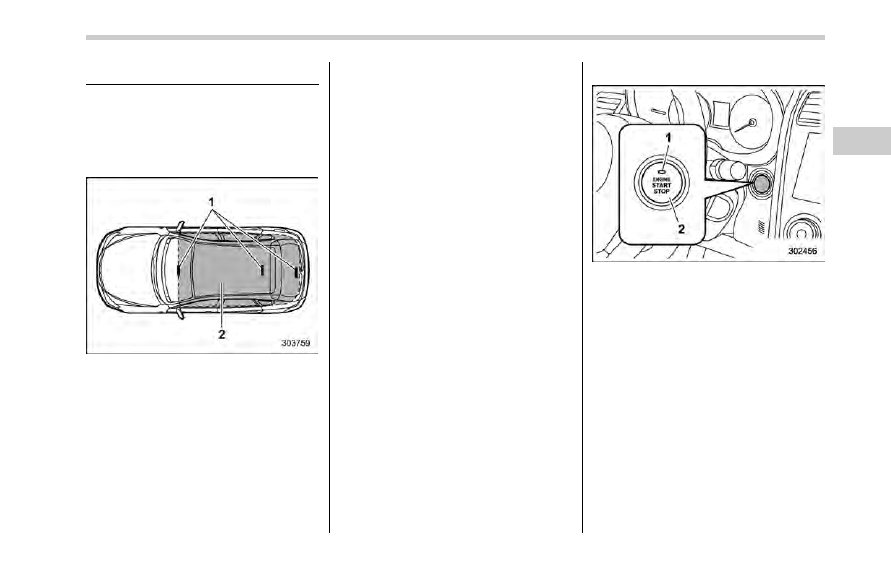
& Operating range for push-
button start system
1)
Antenna
2)
Operating range
NOTE
. If the access key is not detected
within the operating range of the an-
tennas inside the vehicle, the push-
button ignition switch and the hybrid
system start cannot be operated.
. Even when the access key is outside
the vehicle, if it is placed too close to
the glass, it may be possible to switch
the power or to start the hybrid system.
. Do not leave the access key in the
following places. It may become im-
possible to operate the push-button
ignition switch and the hybrid system
start. It may also cause a false warning
to issue although no malfunction actu-
ally occurs, or not to issue a warning
when any malfunction occurs.
– On the instrument panel
– On the floor
– Inside the glove box
– Inside the door trim pocket
– On the rear seat
– At the cargo area
. When operating the push-button
ignition switch or starting the hybrid
system, if the access key battery is
discharged, perform the procedure
described in
“Access key – if access
key does not operate properly
” F9-23.
In such a case, replace the battery
immediately. Refer to
“Replacing ac-
cess key battery
” F11-45.
& Switching power status
1)
Operation indicator
2)
Push-button ignition switch
The power status is switched every time
the push-button ignition switch is pressed.
1. Carry the access key, and sit in the
driver
’s seat.
2. Shift the select lever into the
“P”
position.
3. Press the push-button ignition switch
without depressing the brake pedal. Every
time the button is pressed, the power is
switched in the sequence of
“OFF”,
“ACC”, “ON” and “OFF”. When the hybrid
system is stopped and the push-button
ignition switch is in
“ACC” or “ON”, the
operation indicator on the push-button
ignition switch illuminates in orange.
Instruments and controls/Push
–button ignition switch
– CONTINUED –
3-3
Instruments and controls/Push
–button ignition switch
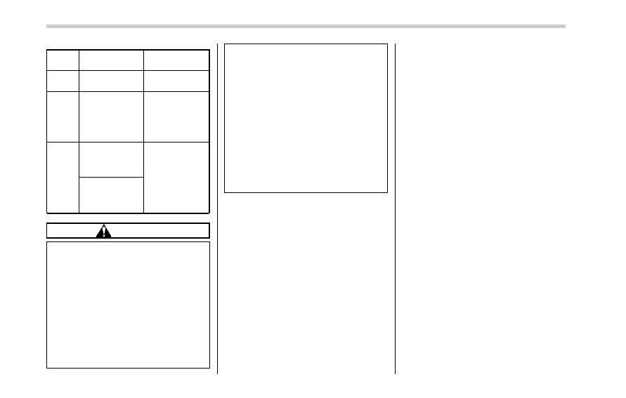
Power
status
Indicator color
Operation
OFF
Turned off
Power is turned
off.
ACC
Orange
The following
systems can be
used:
audio and ac-
cessory power
outlet.
ON
Orange
(while hybrid
system is
stopped)
All electrical
systems can be
used.
Turned off
(while hybrid
system is run-
ning)
CAUTION
. When the push-button ignition
switch is left in
“ON” or “ACC”
for a long time, it may result in 12
V auxiliary battery discharge.
. Do not spill drinks or other
liquids on the push-button igni-
tion switch. It may cause a mal-
function.
. Do not touch the push-button
ignition switch with a hand soiled
with oil or other contaminants. It
may cause a malfunction.
. If the push-button ignition switch
does not operate smoothly, stop
t h e
o p e r a t i o n .
C o n t a c t
a
SUBARU dealer immediately.
. If the push-button ignition switch
does not illuminate even when
the instrument panel illumination
is turned on, have the vehicle
inspected at a SUBARU dealer.
. If the vehicle was left in the hot
sun for a long time, the surface of
the push-button ignition switch
may get hot. Be careful not to
burn yourself.
NOTE
. The push-button ignition switch can-
not be switched to
“OFF” when the
select lever is in a position other than
“P”.
. When operating the push-button
ignition switch, firmly press it all the
way.
. If the push-button ignition switch is
pressed quickly, the power may not
turn on or off.
. If the indicator light on the push-
button ignition switch flashes in green
when the push-button ignition switch is
pressed, steering is locked. When this
occurs, press the push-button ignition
switch while turning the steering wheel
left and right.
! Battery drainage prevention func-
tion
When the push-button ignition switch is
left in the
“ACC” or “ON” position for
approximately 1 hour, the push-button
ignition switch will be automatically
switched to
“OFF” to prevent the battery
from going dead. This function is activated
when the select lever is in the
“P” position.
& When access key does not
operate properly
Refer to
“Access key – if access key does
not operate properly
” F9-23.
3-4
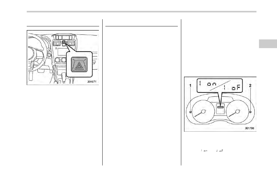
Hazard warning flasher
The hazard warning flasher is used to
warn other drivers when you have to park
your vehicle under emergency conditions.
The hazard warning flasher works regard-
less of the position of the ignition switch.
To turn on the hazard warning flasher,
push the hazard warning button on the
instrument panel. To turn off the flasher,
push the button again.
NOTE
When the hazard warning flasher is on,
the turn signals do not work.
Meters and gauges
NOTE
Some of the meters and gauges on the
combination meter use liquid-crystal
displays. You will find their indications
hard to see if you wear polarized
glasses.
& Combination meter illumina-
tion
When the ignition switch is turned to the
“ON” position, various parts of the combi-
nation meter will illuminate in the following
sequence.
1. Warning lights, indicator lights, meter
needles, gauge needles and liquid crystal
display illuminate.
2. Meter and gauge indications each
show MAX position.
3. Meter and gauge indications each
show MIN position.
4. Regular illumination (for driving) be-
gins.
& Canceling the function for
meter/gauge needle move-
ment upon turning on the
ignition switch
It is possible to activate or deactivate the
movement of the meter needles and
gauge needles that takes place when the
ignition switch is turned to the
“ON”
position. To change the setting, perform
the following procedure.
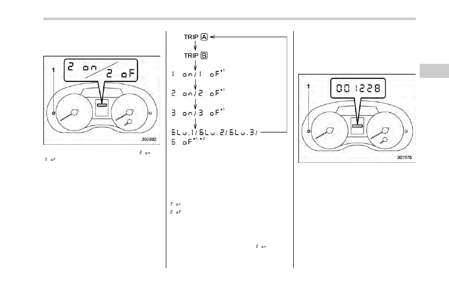
1. Turn the ignition switch to the
“OFF” or
“ACC” position.
1)
Trip knob
2)
Select knob
2. Press the trip knob or the select knob
to show
“
” or “
” on the trip meter
display.
Instruments and controls/Hazard warning flasher
– CONTINUED –
3-5
Instruments and controls/Meters and gauges
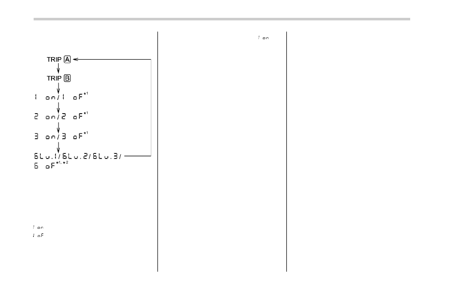
The display can be switched as shown in
the following sequence by pressing the
trip knob.
*1: They cannot be displayed when the
ignition switch is in the
“ON” position.
*2: Displayed only for models with BSD/
RCTA.
To change the current setting, press and
hold the knob for at least 2 seconds.
: Activated
: Deactivated
NOTE
. Your vehicle’s initial movement
setting of the meter/gauge needles
has been set for activation
“
” at
the time of shipment from the factory.
. It is not possible to change the initial
movement setting of the meter/gauge
needles when the ignition switch is in
the
“ON” position. Change the setting
when the ignition switch is in the
“OFF”
or
“ACC” position.
& Meter/Gauge needle illumi-
nation setting
It is possible to activate or deactivate the
illumination of the meter needles and
gauge needles.
When the setting is activated or deacti-
vated, the meter needles and gauge
needles illuminate and turn off as follows.
Activated:
The needles will illuminate and turn off
after approximately 20 seconds when the
driver
’s door is opened while the ignition
switch is in the
“OFF” position.
The illumination of the needles gradually
turns off after the ignition switch is turned
from the
“ON” position to the “OFF”
position.
Deactivated:
The needles will not illuminate when the
driver
’s door is opened while the ignition
switch is in the
“OFF” position.
The illumination of the needles turns off
immediately after the ignition switch is
turned from the
“ON” position to the “OFF”
position.
NOTE
. Even during the illumination after
the driver
’s door is opened, if the
ignition switch is turned to the
“ON”
position, the combination meter will
illuminate as usual.
. If the doors are locked by the remote
keyless entry system or keyless ac-
cess function during the illumination
after the driver
’s door is opened, the
illumination will be turned off.
. Even while the illumination gradu-
ally turns off after the ignition switch is
turned to the
“OFF” position, if the
ignition switch is turned to the
“ON”
position, the combination meter illumi-
nate as usual.
3-6
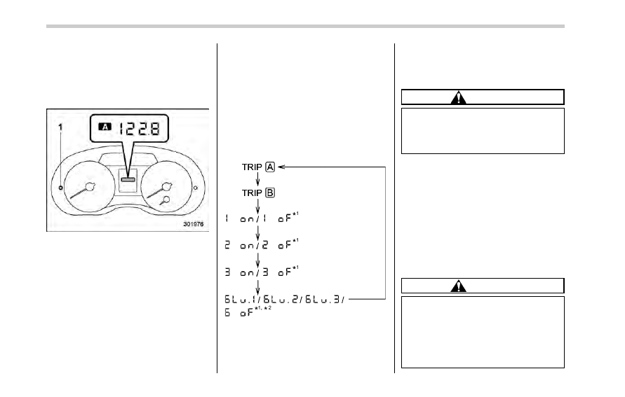
To change the setting:
1. Turn the ignition switch to the
“OFF” or
“ACC” position.
2. Press the trip knob to show
“
” or
“
” on the odometer and trip meter
display. The display can be switched as
shown in the following illustration by
pressing the trip knob.
*1: They cannot be displayed when the
ignition switch is in the
“ON” position.
*2: Displayed only for models with BSD/
RCTA.
3. To change the current setting, press
the trip knob for at least 2 seconds.
: Activated
: Deactivated
NOTE
The initial illumination setting of the
meter/gauge needles of your vehicle
has been set for activation
“
” at the
time of shipment from the factory.
& Speedometer
The speedometer shows the vehicle
speed.
& Odometer
1)
Trip knob
This meter displays the odometer when
the ignition switch is in the
“ON” position.
The odometer shows the total distance
that the vehicle has been driven.
If you press the trip knob when the ignition
switch is in the
“OFF” or “ACC” position,
the odometer/trip meter will light up. If you
do not press the trip knob within 10
seconds of illumination of the odometer/
trip meter, the odometer/trip meter will turn
off.
Instruments and controls/Meters and gauges
– CONTINUED –
3-7
Instruments and controls/Meters and gauges
Also, if you open and close the driver
’s
door within 10 seconds of illumination of
the odometer/trip meter, the odometer/trip
meter will turn off.
& Double trip meter
1)
Trip knob
This meter displays the two trip meters
when the ignition switch is in the
“ON”
position.
The trip meter shows the distance that the
vehicle has been driven since you last set
it to zero.
If you press the trip knob when the ignition
switch is in the
“OFF” or “ACC” position,
the odometer/trip meter will light up. It is
possible to switch between the A trip
meter and B trip meter indications while
the odometer/trip meter is lit up. If you do
not press the trip knob within 10 seconds
of illumination of the odometer/trip meter,
the odometer/trip meter will turn off.
Also, if you open and close the driver
’s
door within 10 seconds of illumination of
the odometer/trip meter, the odometer/trip
meter will turn off.
The display can be switched as shown in
the following sequence by pressing the
trip knob.
*1: They cannot be displayed when the
ignition switch is in the
“ON” position.
*2: Displayed only for models with BSD/
RCTA.
To set the trip meter to zero, select the A
trip or B trip meter by pressing the knob
and keep the knob pressed for more than
2 seconds.
CAUTION
To ensure safety, do not attempt to
change the function of the indicator
during driving, as an accident could
result.
NOTE
If the connection between the combina-
tion meter and battery is broken for any
reason such as vehicle maintenance or
fuse replacement, the data recorded on
the trip meter will be lost.
& Tachometer
The tachometer shows the engine speed
in thousands of revolutions per minute.
CAUTION
Do not operate the hybrid system
with the pointer of the tachometer in
the red zone. In this range, fuel
injection will be cut by the engine
control module to protect the engine
from overrevving. The engine will
resume running normally after the
3-8
engine speed is reduced below the
red zone.
NOTE
To protect the engine/transmission
while the select lever is in the
“P” or
“N” position, the engine is controlled
so that the engine speed may not
become too high even if the accelerator
pedal is pressed hard.
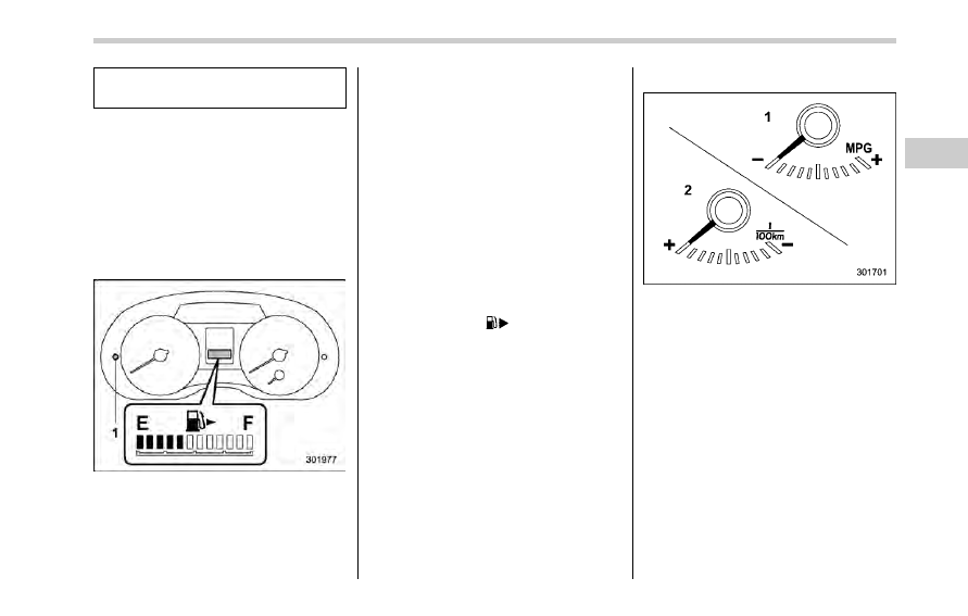
& Fuel gauge
Fuel gauge
1)
Trip knob
The fuel gauge is displayed when the
ignition is in the
“ON” position, and it
shows the approximate amount of fuel
remaining in the tank.
The gauge indication may change slightly
during braking, turning or acceleration due
to fuel level movement in the tank.
If you press the trip knob while the ignition
switch is in the
“OFF” or “ACC” position,
the fuel gauge will light up and indicate the
amount of fuel remaining in the tank. If,
while the fuel gauge is indicating the
amount of fuel remaining in the tank, you
(a) do not press the trip knob for 10
seconds or (b) open and close the driver
’s
door, the fuel gauge indication will turn off.
NOTE
You will see the
“
” sign in the fuel
gauge. This indicates that the fuel filler
door (lid) is located on the right side of
the vehicle.
& ECO gauge (if equipped)
1)
U.S.-spec. models
2)
Except U.S.-spec. models
The ECO gauge shows the difference
between the current rate of fuel consump-
tion and the average rate of fuel consump-
tion since the trip meter was last reset.
If the needle of the gauge moves towards
the right side, this indicates better fuel
efficiency.
NOTE
. The ECO gauge shows only an
approximate indication of fuel effi-
ciency.
. After resetting the trip meter, the
average rate of fuel consumption is not
shown until driving 0.6 mile (1 km).
Instruments and controls/Meters and gauges
– CONTINUED –
3-9
Instruments and controls/Warning and indicator lights
Before that time, the ECO gauge does
not operate.
Warning and indicator lights
& Initial illumination for system
check
Several of the warning and indicator lights
illuminate when the ignition switch is
initially turned to the
“ON” position. This
permits checking the operation of the
bulbs.
Apply the parking brake and turn the
ignition switch to the
“ON” position. For
the system check, the following lights
illuminate and then turn off after several
seconds or after the hybrid system has
started.
: Seatbelt warning light
(The seatbelt warning light turns off
only when the driver fastens the
seatbelt.)
: Front passenger
’s seatbelt warning
light
(The seatbelt warning light turns off
only when the front seat passenger
fastens the seatbelt.)
: SRS airbag system warning light
ON /
: Front passenger
’s frontal airbag
ON indicator light
/
: Front passenger
’s frontal airbag
OFF indicator light
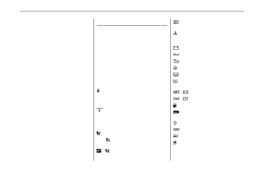
: CHECK ENGINE warning light/Mal-
function indicator light
: Coolant temperature low indicator
light/Coolant temperature high warn-
ing light
: Charge warning light
: Oil pressure warning light
: Engine low oil level warning light
: Windshield washer fluid warning light
: AT OIL TEMP warning light
: Low tire pressure warning light
(U.S.- spec. models)
/
: ABS warning light
/
: Brake system warning light
: Low fuel warning light
: Hill start assist warning light/Hill start
assist OFF indicator light
: Door open warning light
: AWD warning light
: Power steering warning light
: Vehicle Dynamics Control warning
light/Vehicle Dynamics Control opera-
tion indicator light
3-10
: Vehicle Dynamics Control OFF indica-
tor light
: Cruise control indicator light
: Cruise control set indicator light
: Automatic headlight beam leveler
warning light (models with HID head-
lights)
: Access key warning indicator
: Hybrid Fail Lamp
: Pedestrian alert warning light
If any lights fail to illuminate, it indicates a
burned-out bulb or a malfunction of the
corresponding system.
Consult your authorized SUBARU dealer
for repair.
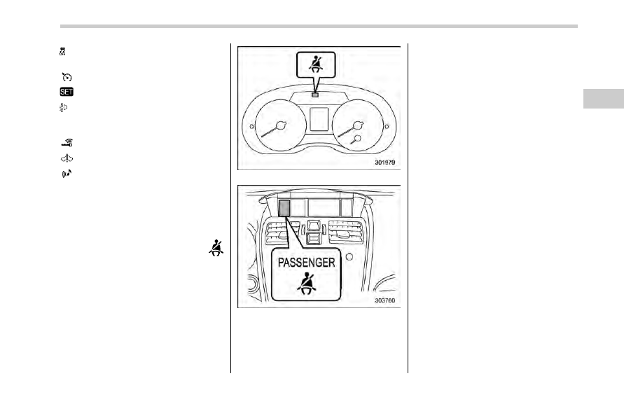
&
Seatbelt warning light
and chime
Your vehicle is equipped with a seatbelt
warning device at the driver
’s and front
passenger
’s seat, as required by current
safety standards.
With the ignition switch turned to the
“ON”
position, this device reminds the driver
and front passenger to fasten their seat-
belts by illuminating the warning lights in
the locations indicated in the following
illustration and sounding a chime.
Driver
’s warning light
Front passenger
’s warning light
! Operation
If the driver and/or front passenger have/
has not yet fastened the seatbelt(s) when
the ignition switch is turned to the
“ON”
position, the seatbelt warning light(s) will
flash for 6 seconds, to warn that the
seatbelt(s) is/are unfastened. If the dri-
ver
’s seatbelt is not fastened, a chime will
also sound simultaneously.
NOTE
. If the driver’s and/or front passen-
ger
’s seatbelt(s) are/is still not fastened
6 seconds later, the seatbelt warning
device operates as follows according
to the vehicle speed.
– At speeds lower than approxi-
mately 9 mph (15 km/h)
The warning light(s) for unfastened
seatbelt(s) will alternate between
steady illumination and flashing at
15-second intervals. The chime will
not sound.
– At speeds higher than approxi-
mately 9 mph (15 km/h)
The warning light(s) for unfastened
seatbelt(s) will alternate between
flashing and steady illumination at
15-second intervals and the chime
will sound while the warning light(s)
is/are flashing.
. It is possible to cancel the warning
Instruments and controls/Warning and indicator lights
– CONTINUED –
3-11
Нет комментариевНе стесняйтесь поделиться с нами вашим ценным мнением.
Текст