Subaru Legacy (2020 year). Instruction — part 12
(159,1)
北米Model "A2570BE-A" EDITED: 2019/ 5/ 24
1. Keep pressing the rear gate opener
button until it is unlocked.
2. Lift up the rear gate.
3. Pull down the rear gate until it starts to
close automatically. The system will be
initialized once the gate is fully closed.
4. Operate the power rear gate and check
that the function operates properly.
!
If the power rear gate is opened
1. Pull down the rear gate until it starts to
close automatically. The system will be
initialized once the gate is fully closed.
2. Operate the power rear gate and check
that the function operates properly.
CAUTION
If the power rear gate function does
not operate properly, have your
vehicle checked by a SUBARU deal-
er.
!
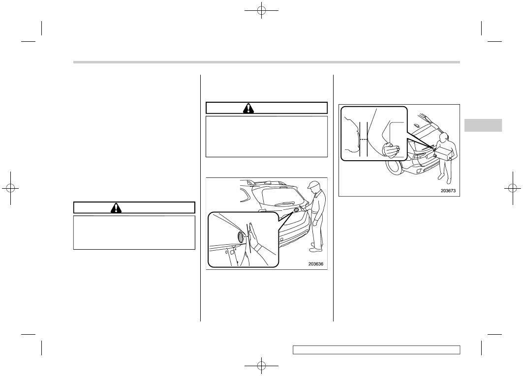
Hands-free Power Rear Gate func-
tion
The Hands-free Power Rear Gate function
enables the rear gate to be opened
automatically by holding a hand over the
rear emblem.
This function can be deactivated using the
Hands-free Power Rear Gate off switch.
Refer to “Hands-free Power Rear Gate off
switch” FP158.
CAUTION
Do not remove the rear emblem or
decorate it or the area around it.
Doing so could lead to a malfunction
of the Hands-free Power Rear Gate
function.
To open the rear gate via the function,
perform the following steps.
1. When the ignition switch is in the OFF
position, carry the access key fob.
2. Move your hand slowly toward the rear
emblem and hold it there until a electronic
chirp sounds.
3. Immediately after the electronic chirp
sounds, move your hand away.
4. The rear gate will open automatically.
NOTE
.
It is possible to open the rear gate by
moving close to the rear emblem.
.
The Hands-free Power Rear Gate
function will not operate when the rear
gate has already been opened.
.
If any of the following are performed
before automatically opening the
power rear gate, the operation will be
canceled.
– Your hand is not properly held
over the rear emblem for approxi-
mately 2 seconds or more.
– Touching the rear emblem
.
The rear gate may suddenly open
– CONTINUED –
Rear Gate (Outback)
157
2
Keys
and
Doors
-------------------------------------------------------------------------------------------------------------------------------------------------------------
(160,1)
北米Model "A2570BE-A" EDITED: 2019/ 5/ 24
under the following circumstances if
someone is holding the access key fob
near the vehicle.
– Washing the vehicle by hand and/
or machine.
– There is an object rearward of the
vehicle in a narrow space.
– Attaching a carrier on the back-
side of the vehicle
– Attaching a trailer
– Removing snow
Take the access key fob out of the
operation range or turn off the function
when you do not want to activate the
Hands-free Power Rear Gate function.
Refer to “Hands-free Power Rear Gate
off switch” FP158.
.
The Hands-free Power Rear Gate
function may not operate properly in
the following conditions.
– In heavy rain
– The rear gate is very dirty.
– The vehicle is covering by snow.
– Hands and arms may not be
detected because of clothing.
– The system of the vehicle cannot
detect the access key fob.
In those cases, push the rear gate
opener button to open.
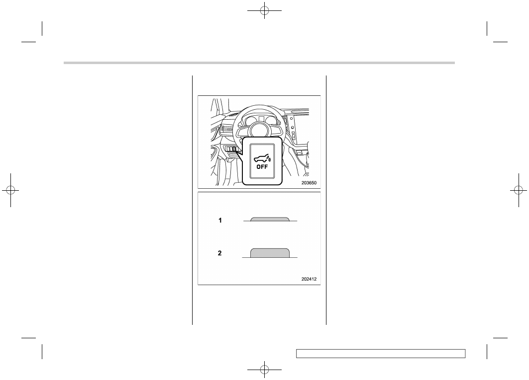
!
Hands-free Power Rear Gate off
switch
Hands-free Power Rear Gate off switch
status
1)
Inactive
2)
Active
Pressing the Hands-free Power Rear Gate
off switch deactivates the Hands-free
Power Rear Gate function.
Rear Gate (Outback)
158
-------------------------------------------------------------------------------------------------------------------------------------------------------------
(161,1)
北米Model "A2570BE-A" EDITED: 2019/ 5/ 24
2-11. Moonroof (If Equipped)
WARNING
Never let anyone’s hands, arms,
head or any objects protrude from
the moonroof. A person could be
seriously injured if the vehicle stops
suddenly or turns sharply or if the
vehicle is involved in an accident.
To avoid serious personal injury
caused by entrapment, you must
conform to the following instruc-
tions without exception.
.
Before closing the moonroof,
make sure that no one’s hands,
arms, head or other objects will
be accidentally caught in the
moonroof.
.
Before leaving the vehicle, al-
ways remove the key from the
ignition switch for safety (models
without “keyless access with
push-button start system”) and
never allow an unattended child
to remain in the vehicle. Failure to
follow this procedure could re-
sult in injury to a child operating
the moonroof.
.
Never try to check the anti-en-
trapment function by deliberately
placing part of your body in the
moonroof.
CAUTION
.
Do not sit on the edge of the open
moonroof.
.
Do not operate the moonroof if
falling snow or extremely cold
conditions have caused it to
freeze shut.
.
The anti-entrapment function
does not operate when the moon-
roof is being tilted down. Be sure
to confirm that it is safe to do so
before tilting the moonroof down.
.
If the moonroof does not close,
have the system checked by a
SUBARU dealer.
The moonroof has both tilting and sliding
functions.
The moonroof operates only when the
ignition switch is in the “ON” position.
&
Moonroof Switches
!
Tilting moonroof
The tilting up function will only operate
when the moonroof is fully closed. The
laying down function will only operate
when the moonroof is tilted.
To tilt up the moonroof:
Press and hold the moonroof switch.
To lay down the moonroof:
Slide and hold the moonroof switch for-
ward.
CAUTION
Release the switch after the moon-
roof has been tilted or has been laid
down completely. Pressing the
– CONTINUED –
Moonroof
159
2
Keys
and
Doors
-------------------------------------------------------------------------------------------------------------------------------------------------------------
(162,1)
北米Model "A2570BE-A" EDITED: 2019/ 5/ 24
switch continuously may cause da-
mage to the moonroof.
NOTE
One-touch operation does not take
place when the moonroof is lowered.
Press the switch continuously to lower
the moonroof.
!
Sliding moonroof
1)
Open
2)
Close
To open the moonroof:
When the moonroof switch is slid and held
backward, the moonroof will open, then
stop slightly before the fully open position
to reduce wind noise.
Slide the moonroof switch again to fully
open the moonroof.
To close the moonroof:
When the moonroof switch is slid and held
to the close side, the moonroof will fully
close.
To stop the moonroof halfway, slide the
moonroof switch either way.
After washing the vehicle or after it rains,
wipe away water on the roof prior to
opening the moonroof to prevent drops of
water from falling into the passenger
compartment.
NOTE
For the sake of safety, it is recom-
mended that you avoid driving with the
moonroof fully opened.
!
Anti-entrapment function
When the moonroof senses a substantial
enough object trapped between its glass
and the vehicle’s roof during closure, it
automatically moves to the open side and
stop. The anti-entrapment function may
also be activated by a strong shock on the
moonroof even when there is nothing
trapped.
CAUTION
Never attempt to test this function
using fingers, hands or other parts
of your body.
&
Sun Shade
The sun shade can be slid forward or
backward by hand while the moonroof is
closed.
If the moonroof is opened, the sun shade
also moves back.
Moonroof
160
-------------------------------------------------------------------------------------------------------------------------------------------------------------
(163,1)
北米Model "A2570BE-A" EDITED: 2019/ 5/ 24
— — — — — — — — — — — — — — — — — — — — — — — — — — — — — — — — — — — — — — — —
— — — — — — — — — — — — — — — — — — — — — — — — — — — — — — — — — — — — — — — —
— — — — — — — — — — — — — — — — — — — — — — — — — — — — — — — — — — — — — — — —
— — — — — — — — — — — — — — — — — — — — — — — — — — — — — — — — — — — — — — — —
— — — — — — — — — — — — — — — — — — — — — — — — — — — — — — — — — — — — — — — —
— — — — — — — — — — — — — — — — — — — — — — — — — — — — — — — — — — — — — — — —
— — — — — — — — — — — — — — — — — — — — — — — — — — — — — — — — — — — — — — — —
— — — — — — — — — — — — — — — — — — — — — — — — — — — — — — — — — — — — — — — —
— — — — — — — — — — — — — — — — — — — — — — — — — — — — — — — — — — — — — — — —
— — — — — — — — — — — — — — — — — — — — — — — — — — — — — — — — — — — — — — — —
— — — — — — — — — — — — — — — — — — — — — — — — — — — — — — — — — — — — — — — —
— — — — — — — — — — — — — — — — — — — — — — — — — — — — — — — — — — — — — — — —
— — — — — — — — — — — — — — — — — — — — — — — — — — — — — — — — — — — — — — — —
-------------------------------------------------------------------------------------------------------------------------------------------------------------
(164,1)
北米Model "A2570BE-A" EDITED: 2019/ 5/ 24
— — — — — — — — — — — — — — — — — — — — — — — — — — — — — — — — — — — — — — — —
— — — — — — — — — — — — — — — — — — — — — — — — — — — — — — — — — — — — — — — —
— — — — — — — — — — — — — — — — — — — — — — — — — — — — — — — — — — — — — — — —
— — — — — — — — — — — — — — — — — — — — — — — — — — — — — — — — — — — — — — — —
— — — — — — — — — — — — — — — — — — — — — — — — — — — — — — — — — — — — — — — —
— — — — — — — — — — — — — — — — — — — — — — — — — — — — — — — — — — — — — — — —
— — — — — — — — — — — — — — — — — — — — — — — — — — — — — — — — — — — — — — — —
— — — — — — — — — — — — — — — — — — — — — — — — — — — — — — — — — — — — — — — —
— — — — — — — — — — — — — — — — — — — — — — — — — — — — — — — — — — — — — — — —
— — — — — — — — — — — — — — — — — — — — — — — — — — — — — — — — — — — — — — — —
— — — — — — — — — — — — — — — — — — — — — — — — — — — — — — — — — — — — — — — —
— — — — — — — — — — — — — — — — — — — — — — — — — — — — — — — — — — — — — — — —
— — — — — — — — — — — — — — — — — — — — — — — — — — — — — — — — — — — — — — — —
-------------------------------------------------------------------------------------------------------------------------------------------------------------
(165,1)
北米Model "A2570BE-A" EDITED: 2019/ 5/ 24
3-1. Ignition Switch (Models without Push-
Button Start System) . . . . . . . . . 166
Key Positions . . . . . . . . . . . . . . 166
Key Reminder Chime . . . . . . . . . . .. 167
Ignition Switch Light. . . . . . . . . . ... 167
3-2. Push-Button Ignition Switch (Models with
Push-Button Start System) . . . . . . .. 168
Safety Precautions. . . . . . . . . . . .. 168
Operating Range for Push-Button Start System... 168
Switching Power Status . . . . . . . . . .. 169
When Access Key Fob Does Not Operate
Properly . . . . . . . . . . . . . . ... 170
3-3. Hazard Warning Flasher. . . . . . . . . 170
3-4. Meters and Gauges . . . . . . . . . . 171
Speedometer . . . . . . . . . . . . . .. 171
Tachometer. . . . . . . . . . . . . . . 171
Odometer . . . . . . . . . . . . . . ... 171
Double Trip Meter . . . . . . . . . . . ... 172
Fuel Gauge. . . . . . . . . . . . . . . 172
Engine Coolant Temperature Gauge . . . . . 173
Combination Meter Settings . . . . . . . . 173
3-5. Illumination Brightness Control . . . . . 173
Auto Dimmer Cancel Function . . . . . . . 174
3-6. Warning and Indicator Lights . . . . . . 175
Seatbelt Warning Light and Chime . . . . . .. 175
SRS Airbag System Warning Light . . . . . .. 177
Front Passenger’s Frontal Airbag ON and OFF
Indicators . . . . . . . . . . . . . . . 177
CHECK ENGINE Warning Light/Malfunction
Indicator Light . . . . . . . . . . . . .. 178
Charge Warning Light . . . . . . . . . . 179
Oil Pressure Warning Light . . . . . . . . 179
Engine Low Oil Level Warning Indicator . . . . 179
AT OIL TEMP Warning Light . . . . . . . ... 180
Low Tire Pressure Warning Light (U.S. Spec.
Models). . . . . . . . . . . . . . . 180
ABS Warning Light. . . . . . . . . . . . 181
Brake System Warning Light . . . . . . . .. 182
Electronic Parking Brake Indicator Light. . . . 183
Auto Vehicle Hold ON Indicator Light . . . . . 184
Auto Vehicle Hold Operation Indicator Light . ... 185
Low Fuel Warning Light . . . . . . . . . . 185
Door Open Indicator. . . . . . . . . . ... 185
Engine Hood Open Warning Light . . . . . .. 185
Windshield Washer Fluid Warning Light . . . . 185
All-Wheel Drive Warning Light . . . . . . . 185
Power Steering Warning Light . . . . . . . 186
Vehicle Dynamics Control Warning Light/
Vehicle Dynamics Control Operation Indicator
Light . . . . . . . . . . . . . . . . 186
Vehicle Dynamics Control OFF Indicator Light . 187
Warning Chimes and Warning Indicator of the
Keyless Access with Push-Button Start
System (If Equipped) . . . . . . . . . . 187
Security Indicator Light . . . . . . . . . .. 192
SI-DRIVE Indicator Light (If Equipped) . . . . 193
Select Lever/Gear Position Indicator . . . . ... 193
Turn Signal Indicator Lights . . . . . . . ... 193
High Beam Indicator Light. . . . . . . . .. 193
High Beam Assist Indicator . . . . . . . . 193
Instruments and Controls
3
Instruments
and
Controls
-------------------------------------------------------------------------------------------------------------------------------------------------------------
(166,1)
北米Model "A2570BE-A" EDITED: 2019/ 5/ 24
Automatic Headlight Beam Leveler Warning
Light (If Equipped) . . . . . . . . . . . 194
LED Headlight Warning Light . . . . . . . .. 194
Steering Responsive Headlight OFF Indicator
Light (If Equipped) . . . . . . . . . . . 194
Steering Responsive Headlight Warning Light
(If Equipped). . . . . . . . . . . . . . 194
Headlight Indicator Light. . . . . . . . . . 194
Front Fog Light Indicator Light (If Equipped). ... 194
Auto Start Stop Warning Light (Yellow) . . . ... 194
Auto Start Stop OFF Indicator Light . . . . . 194
Auto Start Stop Indicator Light (Green) . . . ... 195
Auto Start Stop No Activity Detected Indicator
Light . . . . . . . . . . . . . . . . 195
X-MODE Indicator (Outback) . . . . . . . ... 195
Hill Descent Control Indicator (Outback) . . . . 195
BSD/RCTA Warning Indicator (If Equipped). . .. 195
BSD/RCTA OFF Indicator (If Equipped). . . . 195
Icy Road Surface Warning Indicator . . . . . 196
RAB Warning Indicator (If Equipped). . . . ... 196
RAB OFF Indicator (If Equipped) . . . . . . . 196
Driver Monitoring System Operation Indicator
Light (Green) (If Equipped). . . . . . . . 196
Driver Monitoring System Warning Light
(Yellow) (If Equipped). . . . . . . . . . 196
Driver Monitoring System OFF Indicator Light
(If Equipped). . . . . . . . . . . . . . 196
Driver Monitoring System Temporary Stop
Indicator Light (If Equipped). . . . . . . .. 196
Sonar Audible Alarm OFF Indicator
(If Equipped). . . . . . . . . . . . . . 197
3-7. Combination Meter Display (Color LCD) . ...197
Basic Operation . . . . . . . . . . . . . 198
Welcome Screen (Opening Animation) and
Good-Bye (Ending Animation) Screen. . . ... 198
Warning Screen. . . . . . . . . . . . .. 199
Meter Information Screen . . . . . . . . ... 199
Telltale Screen . . . . . . . . . . . . ... 200
Basic Screens . . . . . . . . . . . . . 201
Digital Speed Screen . . . . . . . . . . .. 204
3-8. Center Information Display (CID) . . . . ...205
Features . . . . . . . . . . . . . . . 205
Welcome Screen . . . . . . . . . . . . 205
Good-Bye Screen . . . . . . . . . . . ... 206
Interruption Screen . . . . . . . . . . . 206
Touch Screen Operations . . . . . . . . ... 206
11.6-inch Display Models (If Equipped) . . . ... 206
Dual 7.0-inch Display Models (If Equipped) . . . 227
3-9. Clock . . . . . . . . . . . . . . . . 239
Setting the Clock Instructionly . . . . . . . . . 239
Setting the Clock Automatically. . . . . . .. 240
3-10. Light Control Switch . . . . . . . . . .241
Headlights . . . . . . . . . . . . . . . 242
High/Low Beam Change (Dimmer) . . . . . .. 244
Headlight Flasher . . . . . . . . . . . ... 244
High Beam Assist Function . . . . . . . . 244
Daytime Running Light System . . . . . . .. 247
3-11. Steering Responsive Headlight (SRH)
(If Equipped) . . . . . . . . . . . . ..248
Instruments and Controls
-------------------------------------------------------------------------------------------------------------------------------------------------------------
(167,1)
北米Model "A2570BE-A" EDITED: 2019/ 5/ 24
3-12. Headlight Beam Leveler (If Equipped) . . 249
3-13. Front Fog Light Switch (If Equipped). . .. 249
3-14. Turn Signal Lever . . . . . . . . . . . 250
One-Touch Lane Changer . . . . . . . . ... 250
3-15. Wiper and Washer . . . . . . . . . . 251
Windshield Wiper and Washer Switches. . . .. 252
Rear Window Wiper and Washer Switch
(Outback) . . . . . . . . . . . . . . . 253
3-16. Defogger and Deicer. . . . . . . . . . 254
3-17. Mirrors . . . . . . . . . . . . . . . 256
Inside Mirror (without Auto-Dimming Function)
(If Equipped) . . . . . . . . . . . . . 256
Auto-Dimming Mirror/Compass with HomeLink
®
(If Equipped) . . . . . . . . . . . . . 256
Outside Mirrors . . . . . . . . . . . . .. 264
3-18. Tilt/Telescopic Steering Wheel . . . . . .267
3-19. Heated Steering Wheel System
(If Equipped) . . . . . . . . . . . . ..267
3-20. Horn. . . . . . . . . . . . . . . . 268
Instruments and Controls
3
Instruments
and
Controls
-------------------------------------------------------------------------------------------------------------------------------------------------------------
(168,1)
北米Model "A2570BE-A" EDITED: 2019/ 5/ 24
3-1. Ignition Switch (Models
without Push-Button Start
System)
WARNING
.
Never turn the ignition switch to
“LOCK” while the vehicle is being
driven or towed because that will
lock the steering wheel, prevent-
ing steering control. And when
the engine is turned off, it takes a
much greater effort than usual to
steer.
.
Before leaving the vehicle, al-
ways remove the key from the
ignition switch for safety and
never allow an unattended child
to remain in the vehicle. Failure to
follow this procedure could re-
sult in injury to a child or others.
Children could operate the power
windows, the moonroof or other
controls or even make the vehicle
move.
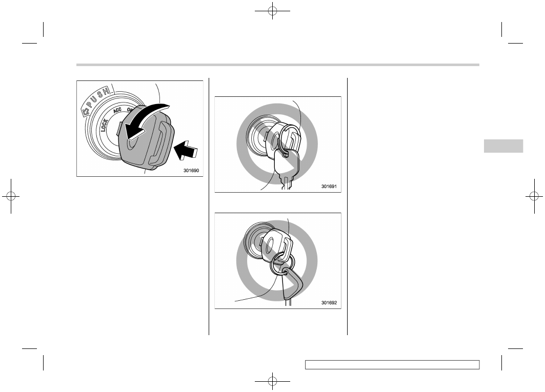
CAUTION
Do not attach a large key holder or
key case to either key. If it banged
against your knees or hands while
you are driving, it could turn the
ignition switch from the “ON” posi-
tion to the “ACC” or “LOCK” posi-
tion, thereby stopping the engine.
Also, if the key is attached to a
keyholder or to a large bunch of
other keys, centrifugal force may act
on it as the vehicle moves, resulting
in unwanted turning of the ignition
switch.
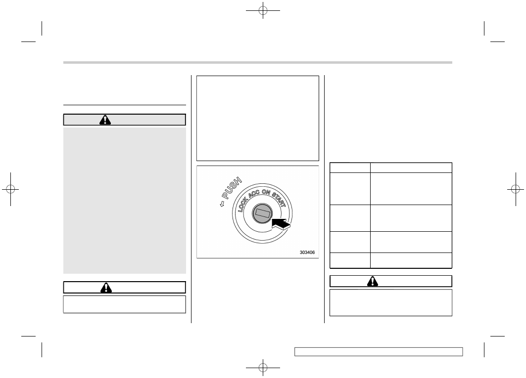
The ignition switch has four positions:
LOCK, ACC, ON and START.
NOTE
.
Keep the ignition switch in the
“LOCK” position when the engine is
not running.
.
Using electrical accessories for a
long time with the ignition switch in the
“ON” or “ACC” position can cause the
battery to go dead.
.
If the ignition switch will not move
from the “LOCK” position to the “ACC”
position, turn the steering wheel
slightly to the left and right as you turn
the ignition switch.
&
Key Positions
Position
Description
LOCK
The key can only be inserted
or removed in this position.
The ignition switch will lock
the steering wheel when you
remove the key.
ACC
In this position the electrical
accessories (audio, acces-
sory power outlet, etc.) can be
used.
ON
This is the normal operating
position after starting the en-
gine.
START
The engine is started in this
position.
CAUTION
Do not turn the ignition switch to the
“START” position while the engine
is running.
Ignition Switch (Models without Push-Button Start System)
166
-------------------------------------------------------------------------------------------------------------------------------------------------------------
(169,1)
北米Model "A2570BE-A" EDITED: 2019/ 5/ 24
NOTE
.
To turn the key from the “ACC” to
“LOCK” position, the select lever must
be in the “P” position and the key must
be pushed in and turned.
.
If your registered key fails to start
the engine, pull out the key once (the
security indicator light will blink), and
then insert the key again and turn it to
the “START” position again to restart
the engine.
.
The engine may not start in the
following cases:
– The key grip is touching another
key or a metallic key holder.
– The key is near another key that
contains an immobilizer transpon-
der.
– The key is near or touching
another transmitter.
&
Key Reminder Chime
The reminder chime sounds when the
driver’s door is opened and the ignition
switch is in the “LOCK” or “ACC” position.
The chime stops under the following
conditions.
.
When the ignition switch is turned to the
“ON” position.
.
When the key is removed from the
ignition switch.
.
When the driver’s door is closed.
&
Ignition Switch Light
For easy access to the ignition switch in
the dark, the ignition switch light illumi-
nates when driver’s door is opened or
when the driver’s door is unlocked using
the remote keyless entry transmitter.
The light remains illuminated for approxi-
mately 30 seconds and gradually turns off
under the following conditions.
.
When the driver’s door is closed
.
When the doors are unlocked using the
remote keyless entry transmitter
– CONTINUED –
Ignition Switch (Models without Push-Button Start System)
167
3
Instruments
and
Controls
-------------------------------------------------------------------------------------------------------------------------------------------------------------
(170,1)
北米Model "A2570BE-A" EDITED: 2019/ 5/ 24
The light gradually turns off under the
following conditions.
.
When the ignition switch is turned to the
“ON” position
.
When the doors are locked using the
remote keyless entry transmitter
3-2. Push-Button Ignition
Switch (Models with Push-
Button Start System)
&
Safety Precautions
Refer to “Safety Precautions” FP114.
&
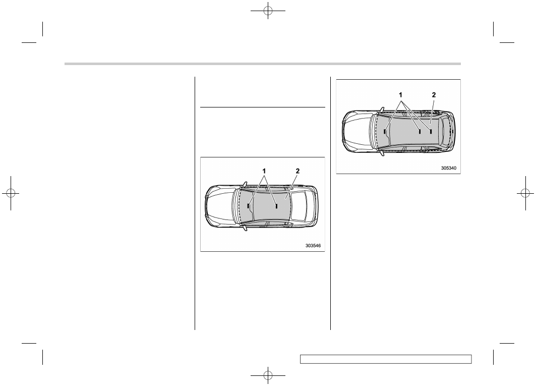
Operating Range for Push-
Button Start System
Legacy
1)
Antenna
2)
Operating range
Outback
1)
Antenna
2)
Operating range
NOTE
.
If the access key fob is not detected
within the operating range of the anten-
nas inside the vehicle, the push-button
ignition switch and the engine start
cannot be operated.
.
Even when the access key fob is
outside the vehicle, if it is placed too
close to the glass, it may be possible to
switch the power or to start the engine.
.
Do not leave the access key fob in
the following places. It may become
impossible to operate the push-button
ignition switch and the engine start.
– On the instrument panel
Push-Button Ignition Switch (Models with Push-Button Start System)
168
-------------------------------------------------------------------------------------------------------------------------------------------------------------
(171,1)
北米Model "A2570BE-A" EDITED: 2019/ 5/ 24
– On the floor
– Inside the glove box
– Inside the door trim pocket
– On the rear seat
– On the rear shelf (Legacy)
– Inside the trunk (Legacy)
– At the corner of the cargo area
(Outback)
.
When operating the push-button
ignition switch or starting the engine,
if the access key fob battery is dis-
charged, perform the procedure de-
scribed in “Access Key Fob – If Access
Key Fob Does Not Operate Properly”
FP456. In such a case, replace the
battery immediately. Refer to “Repla-
cing Battery of Access Key Fob”
FP515.
&
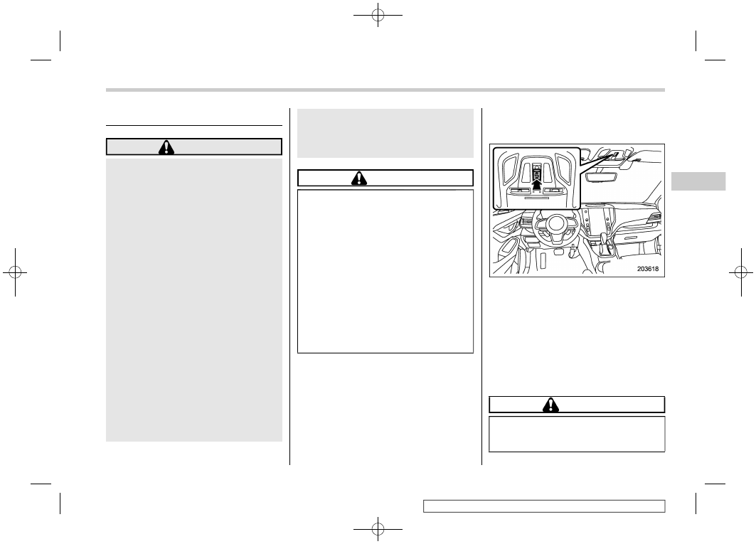
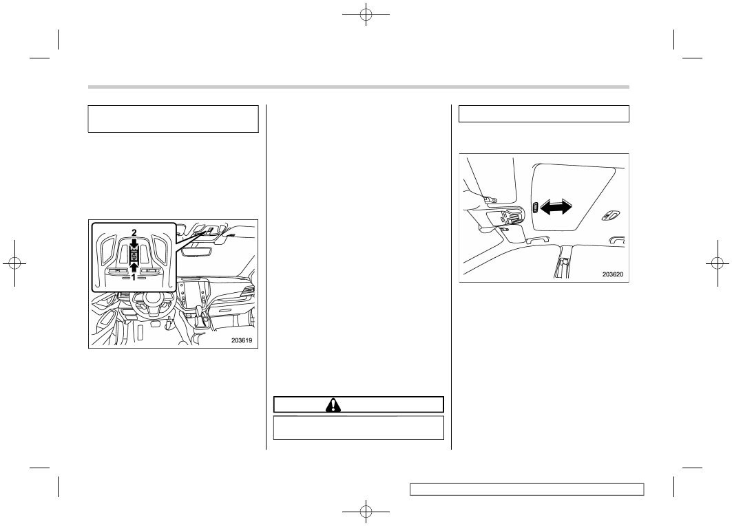
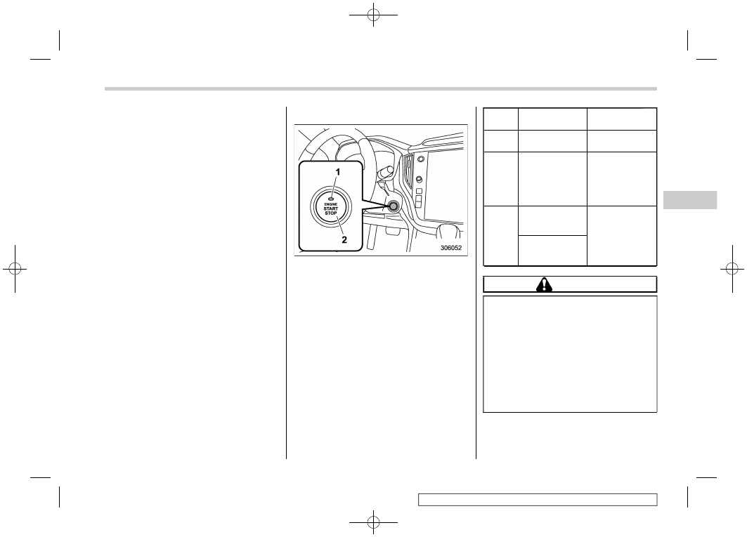
Switching Power Status
1)
Operation indicator
2)
Push-button ignition switch
The power status is switched every time
the push-button ignition switch is pressed.
1. Carry the access key fob, and sit in the
driver’s seat.
2. Make sure the select lever is in the “P”
position.
3. Press the push-button ignition switch
without depressing the brake pedal. Every
time the button is pressed, the power is
switched in the sequence of “OFF”, “ACC”,
“ON” and “OFF”. When the engine is
stopped and the push-button ignition
switch is in “ACC” or “ON”, the operation
indicator on the push-button ignition switch
illuminates in orange.
Power
status
Indicator color
Operation
OFF
Turned off
Power is turned
off.
ACC
Orange
The following
systems can be
used:
audio and ac-
cessory power
outlet.
ON
Orange
(while engine is
stopped)
All electrical
systems can be
used.
Turned off
(while engine is
running)
CAUTION
.
To prevent the vehicle battery
from discharging, do not leave
the push-button ignition switch
in the “ON” or “ACC” position for
a long time.
.
To avoid a malfunction, observe
the following precautions.
– Do not spill drinks or other
liquids on the push-button
ignition switch.
– CONTINUED –
Push-Button Ignition Switch (Models with Push-Button Start System)
169
3
Instruments
and
Controls
-------------------------------------------------------------------------------------------------------------------------------------------------------------
(172,1)
北米Model "A2570BE-A" EDITED: 2019/ 5/ 24
– Do not touch the push-button
ignition switch with a hand
that is soiled with oil or other
contaminants.
.
If the push-button ignition switch
does not operate smoothly, stop
the operation. Contact a SUBARU
dealer immediately.
.
If the operation indicator on the
push-button ignition switch does
not illuminate even when the
instrument panel illumination is
turned on, have the vehicle in-
spected at a SUBARU dealer.
.
If the vehicle was left in the hot
sun for a long time, the surface of
the push-button ignition switch
may get hot. Be careful not to
burn yourself.
NOTE
.
When operating the push-button
ignition switch, firmly press it all the
way.
.
If the push-button ignition switch is
pressed quickly, the power may not
turn on or off.
.
If the indicator light on the push-
button ignition switch flashes in green
when the push-button ignition switch is
pressed, steering is locked. When this
occurs, press the push-button ignition
switch while turning the steering wheel
left and right.
!
Battery drainage prevention func-
tion
When the push-button ignition switch is left
in the “ACC” or “ON” position for approxi-
mately 1 hour, the push-button ignition
switch will be automatically switched to
“OFF” to prevent the battery from going
dead. This function is activated when the
select lever is in the “P” position.
&
When Access Key Fob Does
Not Operate Properly
Refer to “Access Key Fob – If Access Key
Fob Does Not Operate Properly” FP456.
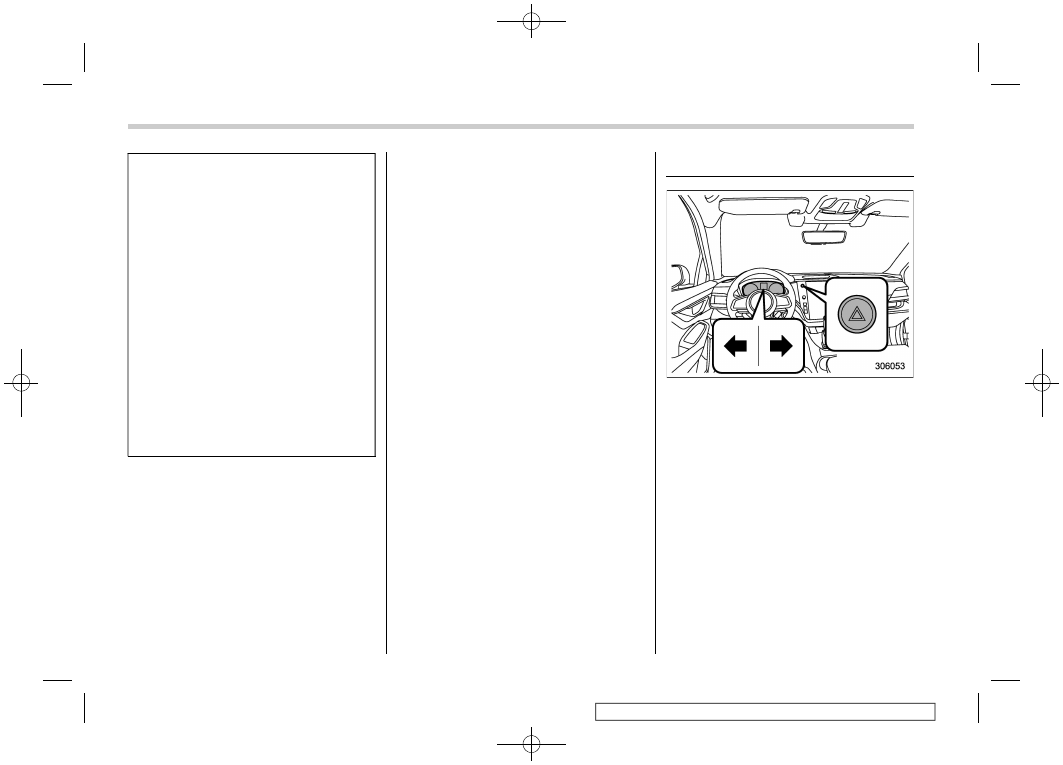
3-3. Hazard Warning Flasher
The hazard warning flasher is used to warn
other drivers when you have to park your
vehicle under emergency conditions. The
hazard warning flasher works with the
ignition switch in any position.
To turn on the hazard warning flasher,
press the hazard warning button on the
instrument panel. All the turn signal lights
and the turn signal indicator lights will
flash. To turn off the flasher, press the
button again.
NOTE
When the hazard warning flasher is on,
the turn signals do not work.
Hazard Warning Flasher
170
-------------------------------------------------------------------------------------------------------------------------------------------------------------
(173,1)
北米Model "A2570BE-A" EDITED: 2019/ 5/ 24
3-4. Meters and Gauges
NOTE
Liquid crystal displays are used in
some of the meters and gauges in the
combination meter. You will find their
indications hard to see if you wear
polarized glasses.
&
Speedometer
The speedometer shows the vehicle
speed.
NOTE
The initial movement of the meter
needles and gauge needles that occurs
when the ignition switch is turned to the
“ON” position can be activated or
deactivated.
For details, refer to “General settings”
FP211 (11.6-inch display models) or
“General settings” FP228 (dual 7.0-
inch display models).
&
Tachometer
The tachometer shows the engine speed
in thousands of revolutions per minute.
CAUTION
Do not operate the engine with the
pointer of the tachometer in the red
zone. In this range, fuel injection will
be cut by the engine control module
to protect the engine from overrev-
ving. The engine will resume run-
ning normally after the engine speed
is reduced below the red zone.
NOTE
The initial movement of the meter
needles and gauge needles that occurs
when the ignition switch is turned to the
“ON” position can be activated or
deactivated.
For details, refer to “General settings”
FP211 (11.6-inch display models) or
“General settings” FP228 (dual 7.0-
inch display models).
&
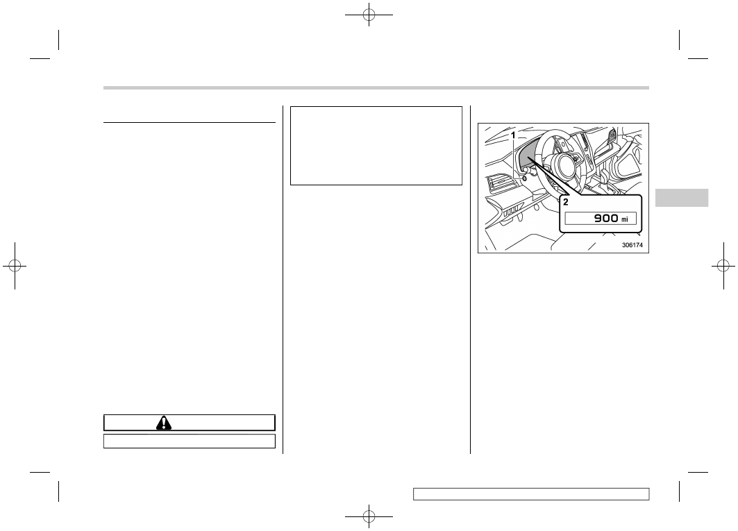
Odometer
1)
TRIP RESET switch
2)
Odometer
This meter displays the odometer when
the ignition switch is in the “ON” position.
The odometer shows the total distance
that the vehicle has been driven.
NOTE
If you press the TRIP RESET switch
when the ignition switch is in the
“LOCK”/“OFF” or “ACC” position, the
odometer/trip meter will light up. The
indicators will turn off when the TRIP
RESET switch is not operated for
approximately 10 seconds.
– CONTINUED –
Meters and Gauges
171
3
Instruments
and
Controls
-------------------------------------------------------------------------------------------------------------------------------------------------------------
(174,1)
北米Model "A2570BE-A" EDITED: 2019/ 5/ 24
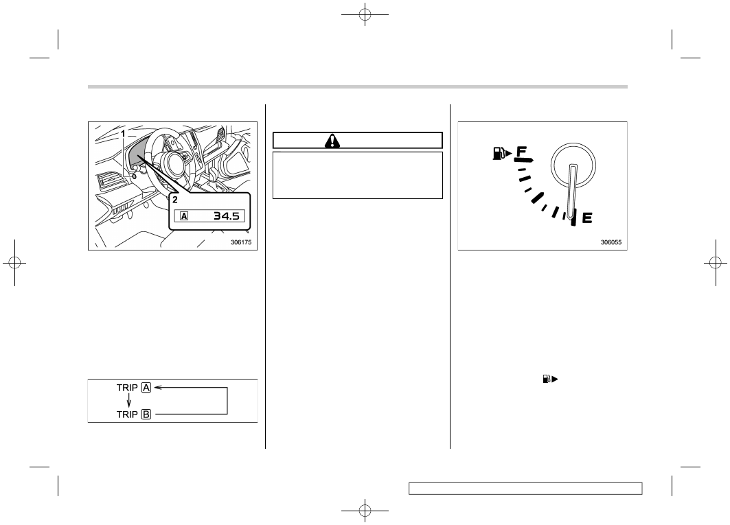
&
Double Trip Meter
1)
TRIP RESET switch
2)
Trip meter
This meter displays the two trip meters
when the ignition switch is in the “ON”
position.
The trip meter shows the distance that the
vehicle has been driven since you last set
it to zero.
The display can be switched as shown in
the following sequence by pressing the
TRIP RESET switch.
To reset the trip meter, select either the A
trip or B trip meter, then press and hold the
TRIP RESET switch.
CAUTION
To ensure safety, do not attempt to
change the function of the indicator
during driving, as an accident could
result.
NOTE
.
If the connection between the com-
bination meter and battery is broken for
any reason such as vehicle mainte-
nance or fuse replacement, the data
recorded on the trip meter will be lost.
.
If you press the TRIP RESET switch
when the ignition switch is in the
“LOCK”/“OFF” or “ACC” position, the
odometer/trip meter will light up. It is
possible to switch between the A trip
meter and B trip meter indications while
the odometer/trip meter is lit up.
In addition, it is possible to reset the trip
meter by pressing and holding the TRIP
RESET switch.
The indicators will turn off when the
TRIP RESET switch is not operated for
approximately 10 seconds.
&
Fuel Gauge
The fuel gauge shows the approximate
amount of fuel remaining in the tank.
When the ignition switch is in the “LOCK”/
“OFF” or “ACC” position, the fuel gauge
shows “E” even if the fuel tank contains
fuel.
The gauge may move slightly due to fuel
level movement in the tank (e.g., during
braking, turning or acceleration).
NOTE
.
You will see the “
” sign in the fuel
gauge. This indicates that the fuel filler
lid is located on the right side of the
vehicle.
.
If you press the TRIP RESET switch
while the ignition switch is in the
Meters and Gauges
172
-------------------------------------------------------------------------------------------------------------------------------------------------------------
Нет комментариевНе стесняйтесь поделиться с нами вашим ценным мнением.
Текст