Subaru Forester (2019). Instruction — part 31
(253,1)
outside mirrors have been cleared and the
windshield blade rubbers have been
deiced completely before that time, press
the control switch to turn them off.
It is possible for the defogger and deicer
system to be set to continuous operation
mode by a SUBARU dealer. Consult your
SUBARU dealer for details. Also, for
models with a combination meter display
(color LCD), it is possible to set the
defogger and deicer system for the con-
tinuous operation mode. For details, refer
to “Vehicle Setting” FP196.
CAUTION
.
To prevent the battery from being
discharged, do not operate the
defogger and deicer system con-
tinuously for any longer than
necessary.
.
Do not use sharp instruments or
window cleaner containing abra-
sives to clean the inner surface of
the rear window. They may da-
mage the conductors printed on
the window.
NOTE
.
Turn on the defogger and deicer
system if the wipers are frozen to the
windshield.
.
If the windshield is covered with
snow, remove the snow so that the
windshield wiper deicer works effec-
tively.
.
While the defogger and deicer sys-
tem is in the continuous operation
mode:
– If the vehicle speed remains at 9
mph (15 km/h) or lower for 15
minutes, the windshield wiper dei-
cer system automatically stops op-
erating. However, the rear window
defogger system and outside mirror
defogger system maintain continu-
ous operation in this condition.
– If the vehicle battery voltage
drops below the permissible level,
continuous operation of the defog-
ger system and deicer system is
canceled and the system stops
operating.
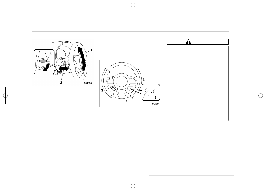
3-19. Tilt/telescopic steering
wheel
WARNING
.
Do not adjust the steering wheel
tilt/telescopic position while driv-
ing. This may cause loss of
vehicle control and result in per-
sonal injury.
.
If the lever cannot be raised to the
fixed position, adjust the steering
wheel again. It is dangerous to
drive without locking the steering
wheel. This may cause loss of
vehicle control and result in per-
sonal injury.
– CONTINUED –
Tilt/telescopic steering wheel
251
3
Instruments
and
controls
-------------------------------------------------------------------------------------------------------------------------------------------------------------
(254,1)
1)
Tilt adjustment
2)
Telescopic adjustment
3)
Tilt/telescopic lock lever
1. Adjust the seat position. Refer to
“Seats” FP32.
2. Pull the tilt/telescopic lock lever down.
3. Move the steering wheel to the desired
level.
4. Pull the lever up to lock the steering
wheel in place.
5. Make sure that the steering wheel is
securely locked by moving it up and down,
and forward and backward.
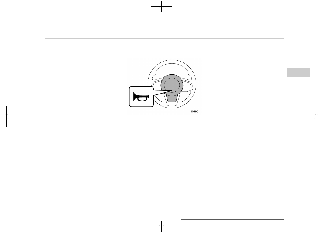
&
Heated Steering Wheel sys-
tem (if equipped)
The Heated Steering Wheel system
warms the steering wheel at a constant
temperature.
1)
Heated Steering Wheel switch
2)
Indicator light
3)
Heated area
To turn on the Heated Steering Wheel
system, pull the Heated Steering Wheel
switch when the ignition switch is in the
“ON” or “ACC” position. Then the steering
wheel will be warmed and the indicator
light on the switch will illuminate. To turn off
the Heated Steering Wheel system, pull
the switch again. Then the indicator light
will turn off.
CAUTION
.
Use the Heated Steering Wheel
system with the engine running.
Otherwise, the battery voltage
may drop below the permissible
level and it may not be possible to
start the engine.
.
There is a possibility that people
with delicate skin may suffer
slight burns even at low tempera-
tures if they use the Heated
Steering Wheel for a long period
of time. When using the Heated
Steering Wheel, always be sure to
warn the persons concerned.
.
Do not cover the Heated Steering
Wheel with an object such as a
steering wheel cover. Doing so
may cause the Heated Steering
Wheel to overheat.
Tilt/telescopic steering wheel
252
-------------------------------------------------------------------------------------------------------------------------------------------------------------
(255,1)
NOTE
.
If the surface temperature of the
steering wheel is approximately above
1048F (408C) when the switch is turned
on, the system will not heat the steering
wheel. Then, the indicator light will
continue to illuminate.
.
The Heated Steering Wheel system
will automatically turn off approxi-
mately 30 minutes after the system
has been turned on.
3-20. Horn
To sound the horn, push the horn pad.
Horn
253
3
Instruments
and
controls
-------------------------------------------------------------------------------------------------------------------------------------------------------------
(258,1)
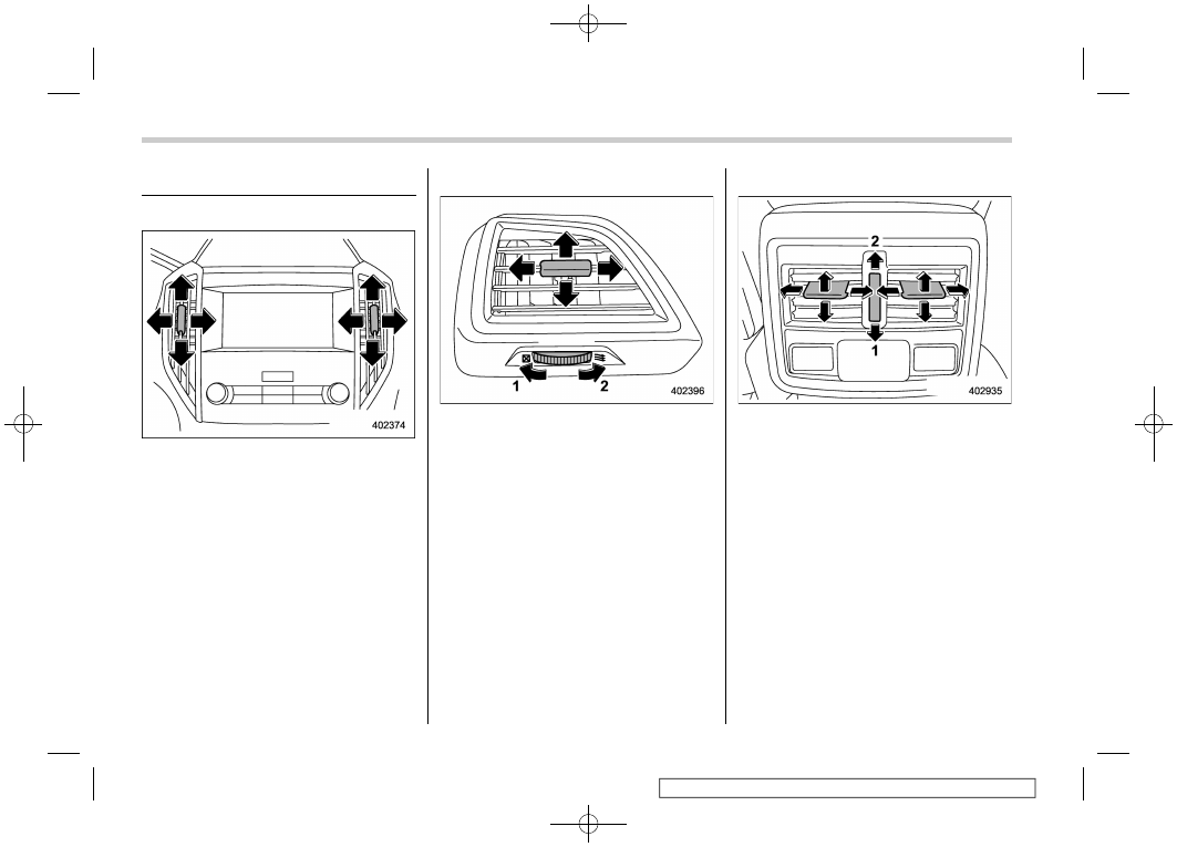
4-1. Ventilator control
&
Center ventilators
Center ventilators
To adjust the airflow direction, move the
tab. To close the ventilator, move the tab all
the way down.
&
Side ventilators
Side ventilators
1)
Close
2)
Open
To adjust the flow direction, move the tab.
&
Rear ventilators
Rear ventilators
1)
Close
2)
Open
To adjust the flow direction, move the tab.
Ventilator control
256
-------------------------------------------------------------------------------------------------------------------------------------------------------------
(259,1)
4-2. Climate control panel
WARNING
.
The cooling function operates
only when the engine is running.
.
Do not leave children or adults
who would normally require the
support of others alone in your
vehicle. Pets should not be left
alone either. On hot, sunny days,
temperatures in a closed vehicle
could quickly become high en-
ough to cause severe or possibly
fatal injuries to people or ani-
mals.
– CONTINUED –
Climate control panel
257
4
Climate
control
-------------------------------------------------------------------------------------------------------------------------------------------------------------
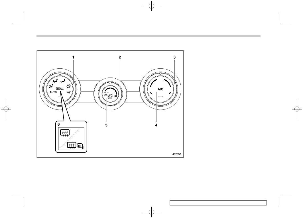
(260,1)
&
Type A
1)
Airflow mode selection dial (Refer to
“Airflow mode selection” FP263.)
2)
Fan speed control dial (Refer to “Fan
speed control” FP264.)
3)
Temperature control dial (Refer to “Tem-
perature control” FP264.)
4)
Air conditioner button (Refer to “Air
conditioner control” FP264.)
5)
Air inlet selection button (Refer to “Air
inlet selection” FP265.)
6)
Rear window defogger button and out-
side mirror defogger button (if equipped)
(Refer to “Defogger and deicer” FP250.)
NOTE
The controllable temperature range
may vary depending on the regional
specifications of the vehicle.
Climate control panel
258
-------------------------------------------------------------------------------------------------------------------------------------------------------------
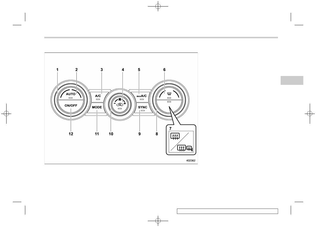
(261,1)
&
Type B
1)
Driver’s side temperature control dial
(Refer to “Automatic climate control
operation” FP261 and/or “Temperature
control” FP264.)
2)
AUTO button (Refer to “Automatic cli-
mate control operation” FP261.)
3)
Air conditioner button (Refer to “Air
conditioner control” FP264.)
4)
Air inlet selection button (Refer to “Air
inlet selection” FP265.)
5)
MAX A/C button (Refer to “MAX A/C
mode” FP264.)
6)
Defroster button (Refer to “Defrosting”
FP265.)
7)
Rear window defogger button and out-
side mirror defogger button (if equipped)
(Refer to “Defogger and deicer” FP250.)
8)
Passenger’s side temperature control
dial (Refer to “Temperature control”
FP264.)
9)
SYNC button (Refer to “SYNC mode”
FP264.)
10) Fan speed control dial (Refer to “Fan
11) Airflow mode selection button (Refer to
“Airflow mode selection” FP263.)
12) ON/OFF button (Refer to “Automatic
climate control operation” FP261.)
NOTE
The climate control screen is displayed
on the multi-function display (color
LCD). Refer to “Climate control screen”
FP206.
– CONTINUED –
Climate control panel
259
4
Climate
control
-------------------------------------------------------------------------------------------------------------------------------------------------------------
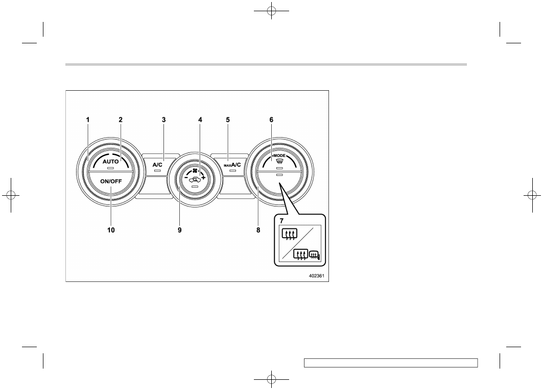
(262,1)
&
Type C
1)
Temperature control dial (Refer to “Auto-
matic climate control operation” FP261
and/or “Temperature control” FP264.)
2)
AUTO button (Refer to “Automatic cli-
mate control operation” FP261.)
3)
Air conditioner button (Refer to “Air
conditioner control” FP264.)
4)
Air inlet selection button (Refer to “Air
inlet selection” FP265.)
5)
MAX A/C button (Refer to “MAX A/C
mode” FP264.)
6)
Defroster button (Refer to “Defrosting”
FP265.)
7)
Rear window defogger button and out-
side mirror defogger button (if equipped)
(Refer to “Defogger and deicer” FP250.)
8)
Airflow mode selection dial (Refer to
“Airflow mode selection” FP263.)
9)
Fan speed control dial (Refer to “Fan
speed control” FP264.)
10) ON/OFF button (Refer to “Automatic
climate control operation” FP261.)
NOTE
The climate control screen is displayed
on the multi-function display (color
LCD). Refer to “Climate control screen”
FP206.
Climate control panel
260
-------------------------------------------------------------------------------------------------------------------------------------------------------------
Нет комментариевНе стесняйтесь поделиться с нами вашим ценным мнением.
Текст