Suzuki Grand Vitara JB627. Service manual — part 180
4E-1 ABS:
Brakes
ABS
Precautions
Precautions in Diagnosing Troubles
S6JB0B4500001
To ensure that the trouble diagnosis is done accurately
and smoothly, observe the following and follow “ABS
Check”.
• If the vehicles was operated in any of the following
ways, ABS warning light may light momentarily but
this does not indicate anything abnormal in ABS.
– The vehicle was driven with parking brake pulled.
– The vehicle was driven with brake dragging.
– The vehicle was stuck in mud, sand, etc.
– Wheel spin occurred while driving.
– Wheel(s) was rotated while the vehicle was jacked
up.
• Be sure to read “Precautions for Electrical Circuit
Service in Section 00” before inspection and observe
what is written there.
• Be sure to use the trouble diagnosis procedure as
described in “ABS Check”. Failure to follow it may
result in incorrect diagnosis. (Some other diagnosis
trouble code may be stored by mistake in the memory
of ABS (ESP
®) control module during inspection.)
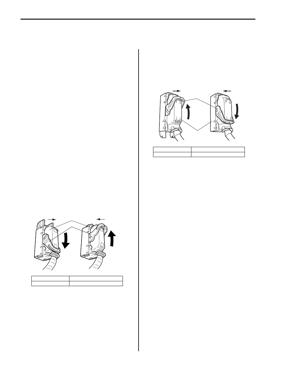
• When disconnecting ABS (ESP
®) hydraulic unit /
control module connector (1), pull down lock lever (2)
of connector.
When connecting, set the connector on ABS (ESP
®)
hydraulic unit / control module assembly and pull up
the lock lever (2) until it locks.
• When disconnecting ESP
® hydraulic unit / control
module connector (1), pull up lock lever (2) of
connector.
When connecting, set the connector on ESP
®
hydraulic unit / control module assembly and pull
down the lock lever (2) until it locks.
• Communication of ECM, TCM (A/T model), BCM,
ABS (ESP
®) control module, 4WD control module (if
equipped), keyless start control module (if equipped)
and combination meter is established by CAN
(Controller Area Network).
Therefore, be sure to read “Precaution for CAN
Communication System in Section 00” before
inspection and handle CAN communication line.
Precautions in On-Vehicle Service
S6JB0B4500002
When connector is connected to ABS (ESP
®) hydraulic
unit / control module assembly, do not disconnect
connectors of sensors with ignition switch ON.
Otherwise, DTC will be set in ABS (ESP
®) control
module.
Precautions in Hydraulic Unit Operation Check
S6JB0B4500003
ABS (ESP
®) hydraulic unit / control module assembly
function is checked by correct wheel release condition
when brake pressure is depressurized using SUZUKI
scan tool. The hydraulic unit operation check referring to
“Hydraulic Unit Operation Check” should be performed
to confirm the correct brake pipe connection in the
following cases.
• ABS (ESP
®) hydraulic unit / control module ABS
(ESP
®) hydraulic unit / control module assembly was
replaced.
• Brake pipe and/or hose were replaced.
[A]: Disconnect
C: Pull down to disconnect
[B]: Connect
D: Pull up to connect
2
1
C
D
[A]
[B]
I4RH01450001-01
[A]: Disconnect
C: Pull up to disconnect
[B]: Connect
D: Pull down to connect
2
1
[A]
[B]
C
D
I6JB01450001-02
ABS: 4E-2
General Description
ABS Description
S6JB0B4501001
The ABS (Antilock Brake System) controls the fluid
pressure applied to the wheel cylinder of each brake
from the master cylinder so that each wheel is not locked
even when hard braking is applied.
This ABS has also the following function.
While braking is applied, but before ABS control
becomes effective, braking force is distributed between
the front and rear so as to prevent the rear wheels from
being locked too early for better stability of the vehicle.
The main component parts of this ABS include the
following parts in addition to those of the conventional
brake system.
• Wheel speed sensor which senses revolution speed
of each wheel and outputs its signal.
• ABS warning light which lights to inform abnormality
when system fails to operate properly.
• ABS (ESP
®) hydraulic unit / control module assembly
is incorporated ABS (ESP
®) control module, ABS
hydraulic unit (actuator assembly), solenoid valve
power supply driver (transistor), solenoid valve driver
(transistor), pump motor driver (transistor).
– ABS (ESP
®) control module which sends operation
signal to ABS hydraulic unit to control fluid pressure
applied to each wheel cylinder based on signal
from each wheel speed sensor so as to prevent
wheel from locking.
– ABS hydraulic unit which operates according to
signal from ABS (ESP
®) control module to control
fluid pressure applied to wheel cylinder of each 4
wheels.
– Solenoid valve power supply driver (transistor)
which supplies power to solenoid valve in ABS
hydraulic unit.
– Solenoid valve driver (transistor) which controls
each solenoid valves in ABS hydraulic unit.
– Pump motor driver (transistor) which supplies
power to pump motor in ABS hydraulic unit.
This ABS is equipped with Electronic Brake force
Distribution (EBD) system that controls a fluid pressure
of rear wheels to best condition, which is the same
function as that of proportioning valve, by the signal from
wheel sensor independently of change of load due to
load capacity and so on. And if the EBD system fails to
operate properly, the brake warning light lights to inform
abnormality.
ABS (ESP
®) hydraulic unit / control module
Assembly Description
S6JB0B4501002
ABS (ESP
®) control module is a component of ABS
(ESP
®) hydraulic unit / control module assembly and
has the following functions.
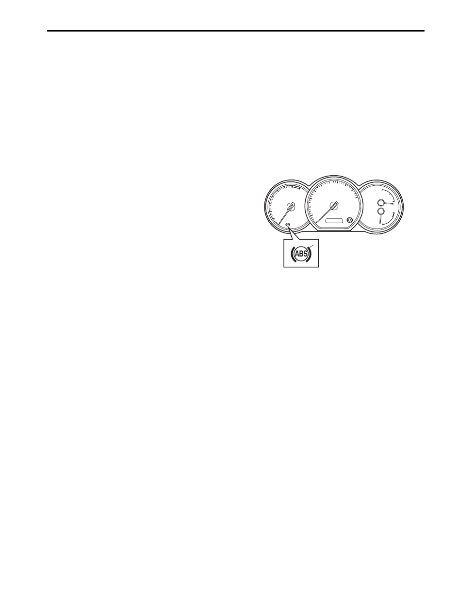
Self-Diagnosis Function
ABS (ESP
®) control module diagnoses conditions of the
system component parts (whether or not there is any
abnormality) all the time and indicates the results
(warning of abnormality occurrence and DTC) through
the ABS warning light (1) as described.
• When ignition switch is turned ON, ABS warning light
lights for 2 seconds to check its circuit.
• When no abnormality has been detected (the system
is in good condition), ABS warning light turns OFF
after 2 seconds.
• When an abnormality in the system is detected, ABS
warning light lights and the area where that
abnormality lies is stored in the memory of EEPROM
in ABS (ESP
®) control module.
1
I5JB0A450001-01
4E-3 ABS:
CAN Communication System Description
S6JB0B4501003
Refer to “CAN Communication System Description in Section 1A” for CAN communication system description.
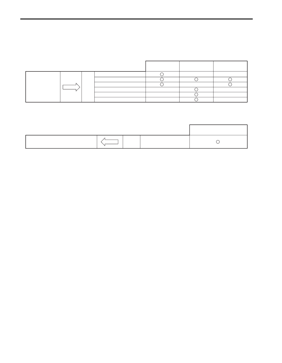
ABS communicates control data with each control module as follows.
ABS Transmission Data
ABS Reception Data
Torque request signal
Wheel speed signal
ABS active
ABS indication on
EBD indication on
ABS diagnostic trouble codes
Combination Meter
Transmit
DATA
ABS hydraulic
unit / control module
assembly
ECM
4WD control module
(if equiped)
I5JB0A450002-03
Brake pedal switch active
Receive
DATA
ABS hydraulic unit / control module assembly
ECM
I5JB0A450003-03
ABS: 4E-4
Schematic and Routing Diagram
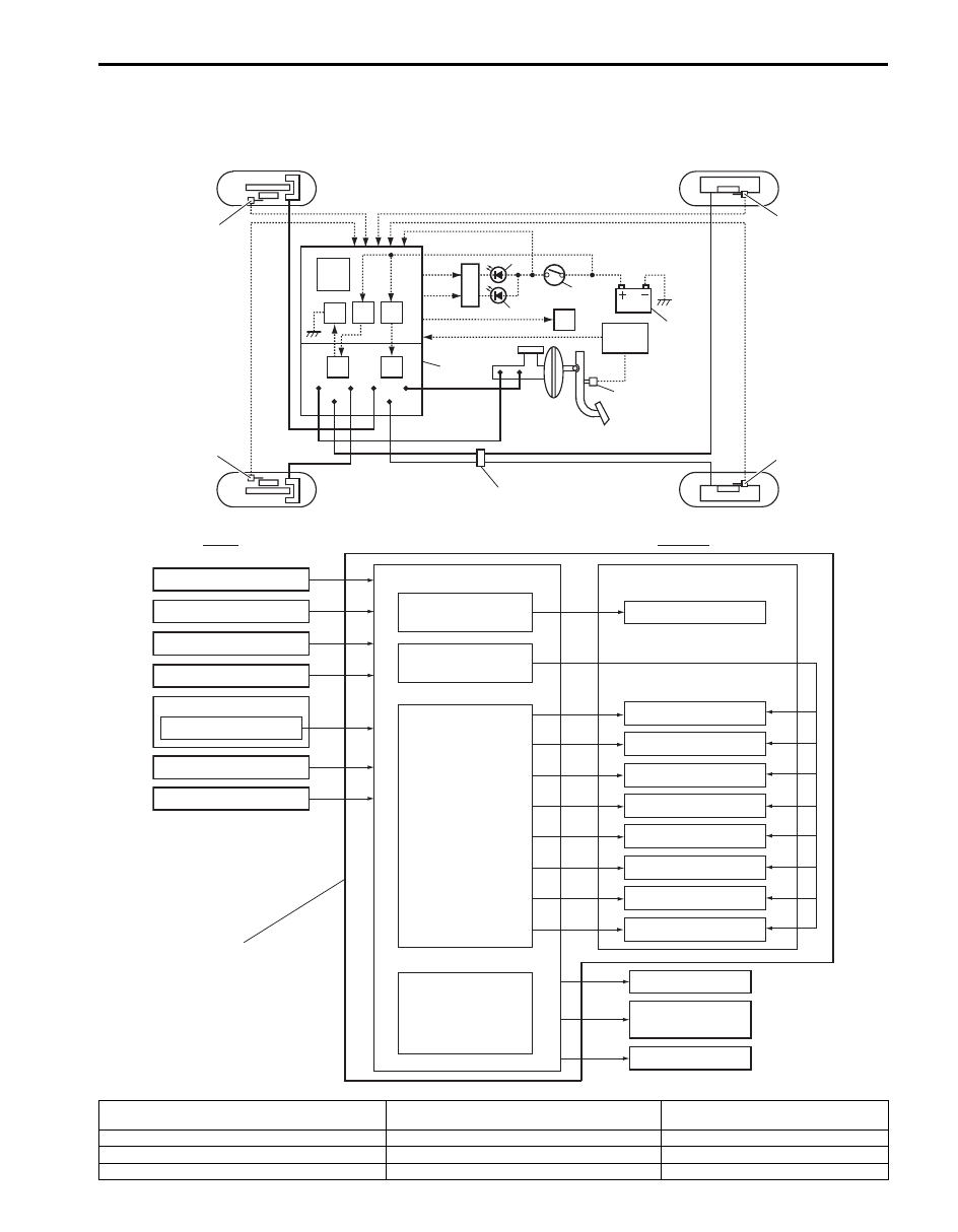
ABS Schematic
S6JB0B4502001
INPUT
OUTPUT
ABS control module
Wheel speed sensor (LF)
Wheel speed sensor (LR)
Wheel speed sensor (RF)
Battery Voltage
Ignition Voltage
Pump motor
driver (transistor)
Solenoid valve power
supply driver (transistor)
Solenoid valve
driver (transistor)
Hydraulic unit
Pump motor
LF inlet solenoid valve
LF outlet solenoid valve
LR inlet solenoid valve
LR outlet solenoid valve
RF inlet solenoid valve
RF outlet solenoid valve
RR inlet solenoid valve
RR outlet solenoid valve
ABS warning
EBD warning
(Brake warning)
Data link connector
ABS hydraulic unit/control
module assembly
Wheel speed sensor (RR)
Stop lamp switch
3
7
2
6
4
5
8
12
13
ECM
G sensor (4WD model)
21
20
14
15
1
22
17
16
18
19
11
10
9
I6JB0B450001-02
1. ABS (ESP
®) hydraulic unit / control module
assembly
9. Brake light switch
17. Wheel speed sensor (Left-rear)
2. ABS (ESP
®) control module
10. ABS warning light
18. Battery
3. ABS (ESP
®) hydraulic unit
11. EBD warning light (Brake warning light)
19. Ignition switch
4. Solenoid valve power supply driver (transistor)
12. Light driver module
20. G sensor (4WD model)
Нет комментариевНе стесняйтесь поделиться с нами вашим ценным мнением.
Текст