Suzuki Grand Vitara JB627. Service manual — part 316
8B-90 Air Bag System:
DTC B1333 / B1337: Left / Right Side Curtain-Air Bag Initiator Circuit Short to Ground
S6JB0B8204038
Wiring Diagram
Refer to “DTC B1331 / B1335: Left / Right Side Curtain-Air Bag Initiator Circuit Resistance High”.
CAUTION
!
Be sure to observe instructions under CAUTION in “Air Bag Diagnostic System Check Flow”.
DTC Will Set when
The voltage measured at side curtain-air bag (left or right) initiator circuit is below a specified value for specified time.
Flow Test Description
Step 1: Check whether malfunction is in side curtain-air bag (inflator) module.
Step 2: Check side curtain-air bag initiator circuit.
DTC Troubleshooting
Step
Action
Yes
No
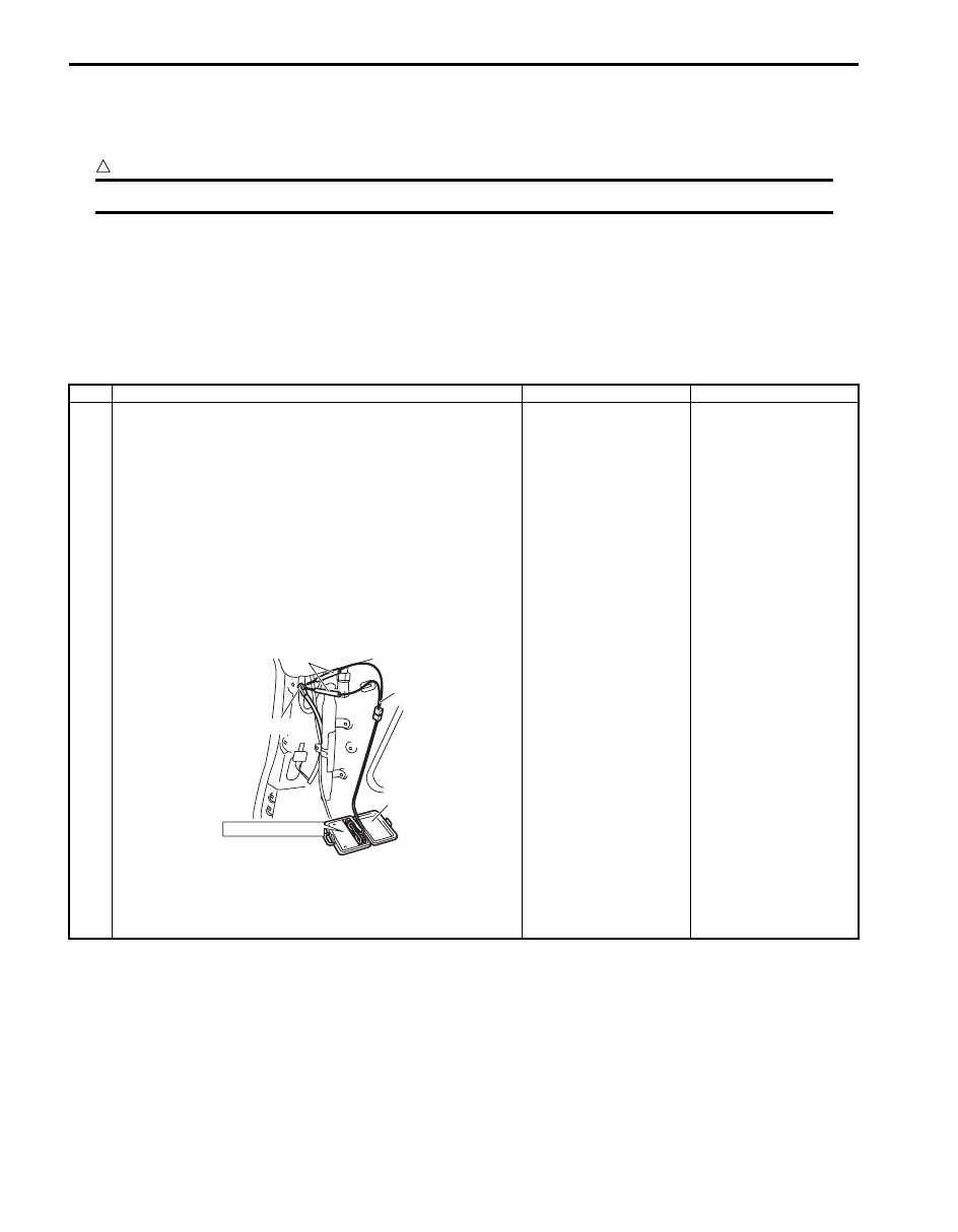
1
1) With ignition switch OFF, remove rear side upper trim of
left or right side and disconnect side curtain-air bag
(inflator) module connector.
2) Check proper connection to side-air bag (inflator)
module at terminals in “G18” or “G41” connector.
3) If OK, then connect special tools (A), (B) and (C) to side
curtain-air bag (inflator) module connector.
Special tool
(A): 09932–76010
(B): 09932–75010
(C): 09932–78310
4) Check SDM DTC.
With ignition switch ON, is DTC B1333 or B1337 still
indicated?
Go to Step 2.
Replace side curtain-air
bag (inflator) module
referring to “Side
Curtain-Air Bag
(Inflator) Module
Removal and
Installation”.
STEERING WHEEL
(B)
(C)
(A)
“G18”, “G41”
I5JB0A820057-01
Air Bag System: 8B-91
NOTE
Upon completion of inspection and repair work, perform the following items.
• Reconnect all air bag system components, ensure all components are properly mounted.
• Clear DTCs referring to “DTC Clearance”, if any.
• Repeat “Air Bag Diagnostic System Check” to confirm that the trouble has been corrected.
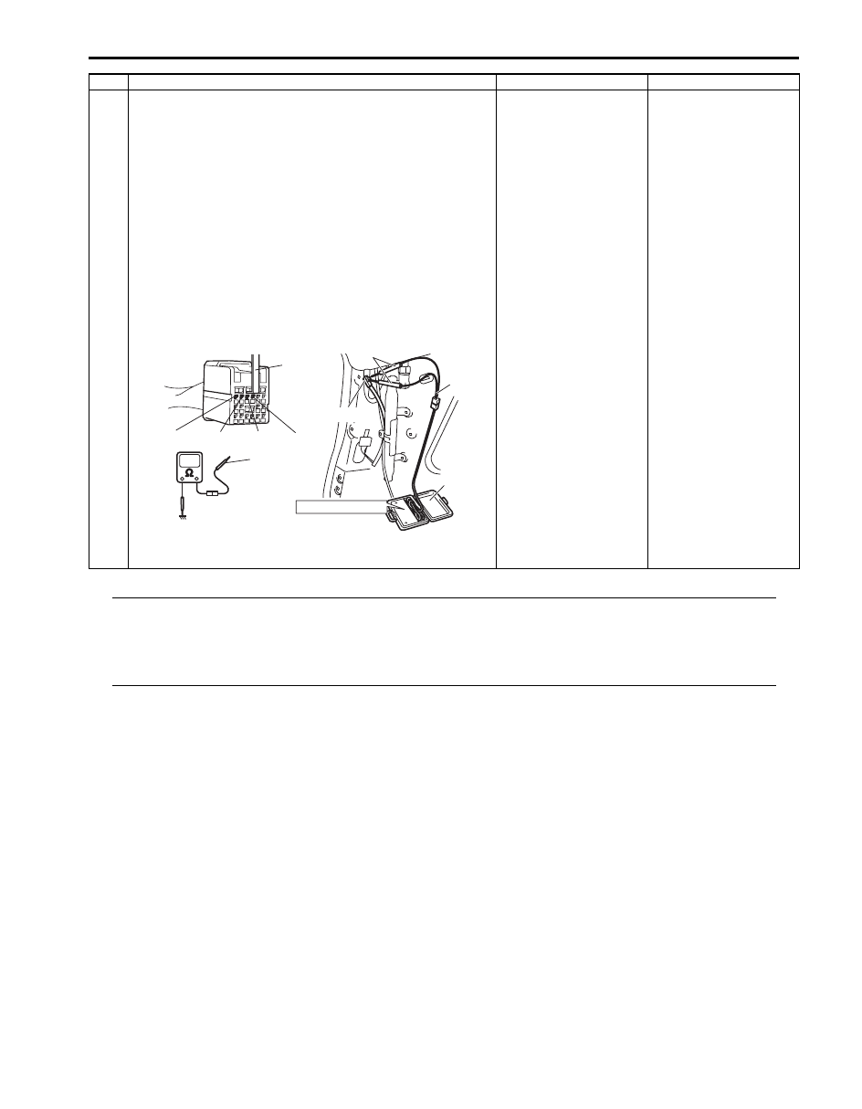
2
1) With ignition switch OFF, disconnect SDM connector
“L32”.
2) Release shorting bar in SDM connector inserting release
tool (1) included in special tool (A).
3) Measure resistance between “L32-1” and body ground,
and between “L32-2” and body ground (for DTC B1333)
or “L32-3” and body ground, and between “L32-4” and
body ground (for DTC B1337) with connected special
tools (A), (B) and (C).
Special tool
(A): 09932–76010
(B): 09932–75010
(C): 09932–78310
Is resistance infinity?
Substitute a known-
good SDM and recheck.
DTC B1333: Repair
short from “YEL/GRN”
or “YEL/BLU” wire
circuit to ground.
DTC B1337: Repair
short from “BLK/YEL” or
“BRN/YEL” wire circuit
to ground.
Step
Action
Yes
No
STEERING WHEEL
(B)
(C)
(A)
“G18”, “G41”
“L32-1”
“L32-2” “L32-3” “L32-4”
(A)
1, (A)
I5JB0A820059-01

8B-92 Air Bag System:
DTC B1334 / B1338: Left / Right Side Curtain-Air Bag Initiator Circuit Short to Power Circuit
S6JB0B8204039
Wiring Diagram
Refer to “DTC B1331 / B1335: Left / Right Side Curtain-Air Bag Initiator Circuit Resistance High”.
CAUTION
!
Be sure to observe instructions under CAUTION in “Air Bag Diagnostic System Check Flow”.
DTC Will Set when
The voltage measured at side curtain-air bag (left or right) initiator circuit is above a specified value for specified time.
Flow Test Description
Step 1: Check whether malfunction is in side curtain-air bag (inflator) module.
Step 2: Check side curtain-air bag initiator circuit.
DTC Troubleshooting
Step
Action
Yes
No
1
1) With ignition switch OFF, remove rear side upper trim of
left or right side and disconnect side curtain-air bag
(inflator) module connector.
2) Check proper connection to side curtain-air bag (inflator)
module at terminals in “G18” or “G41” connector.
3) If OK, then connect special tools (A), (B) and (C) to side
curtain-air bag (inflator) module connector.
Special tool
(A): 09932–76010
(B): 09932–75010
(C): 09932–78310
4) Check SDM DTC.
With ignition switch ON, is DTC B1334 or B1338 still
indicated?
Go to Step 2.
Replace side curtain-air
bag (inflator) module
referring to “Side
Curtain-Air Bag
(Inflator) Module
Removal and
Installation”.
STEERING WHEEL
(B)
(C)
(A)
“G18”, “G41”
I5JB0A820057-01
Air Bag System: 8B-93
NOTE
Upon completion of inspection and repair work, perform the following items.
• Reconnect all air bag system components, ensure all components are properly mounted.
• Clear DTCs referring to “DTC Clearance”, if any.
• Repeat “Air Bag Diagnostic System Check” to confirm that the trouble has been corrected.
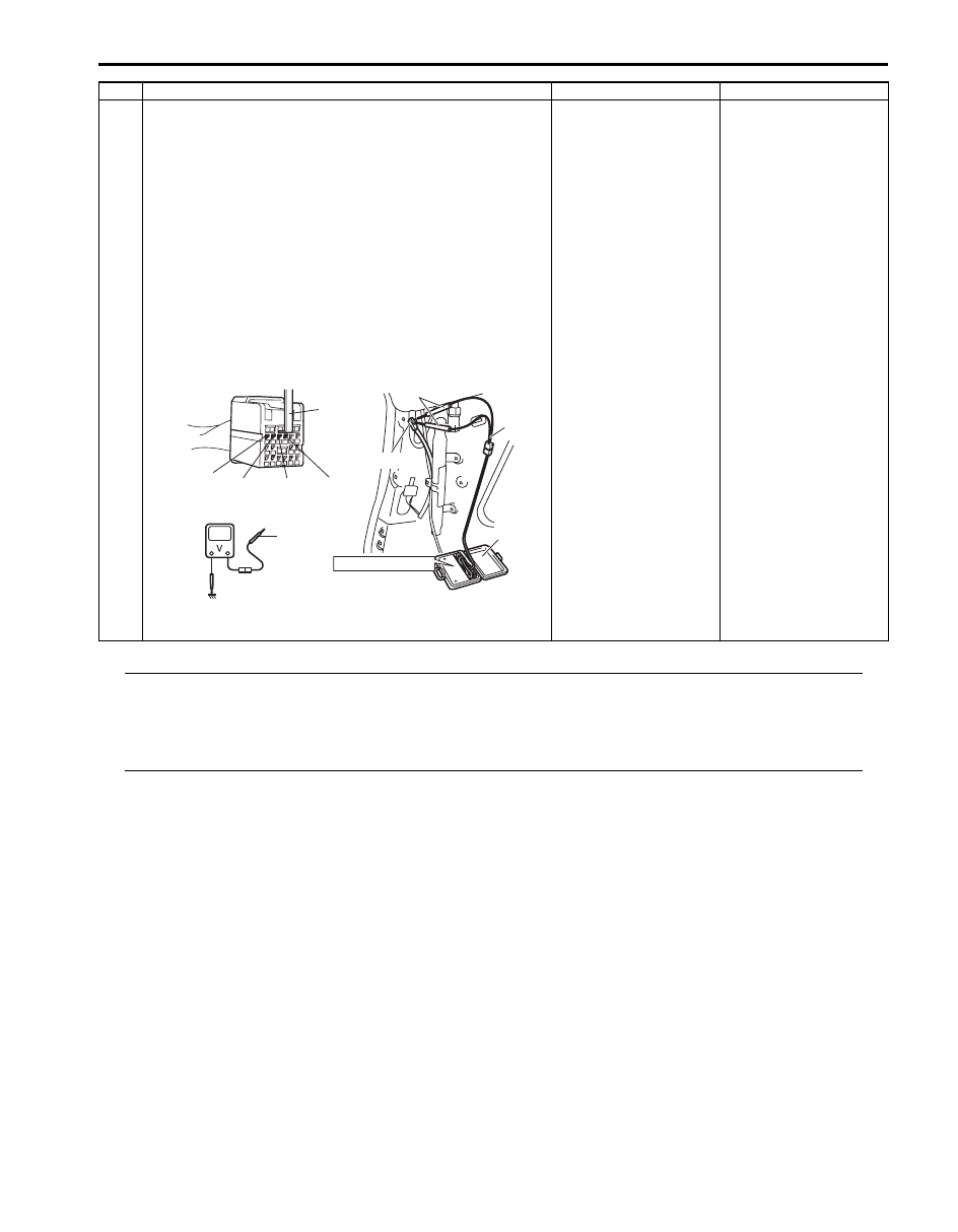
2
1) With ignition switch OFF, disconnect SDM connector
“L32”.
2) Release shorting bar in SDM connector inserting release
tool (1) included in special tool (A).
3) Measure voltage between “L32-1” and body ground, and
between “L32-2” and ground (for DTC B1334) or “L32-3”
and body ground, and between “L32-4” and body ground
(for DTC B1338) with connected special tools (A), (B)
and (C).
Special tool
(A): 09932–76010
(B): 09932–75010
(C): 09932–78310
With ignition switch ON, is voltage 4 V or less?
Substitute a known-
good SDM and recheck.
DTC B1034: Repair
short from “YEL/GRN”
or “YEL/BLU” wire
circuit to power circuit.
DTC B1038: Repair
short from “BLK/YEL” or
“BRN/YEL” wire circuit
to power circuit.
Step
Action
Yes
No
STEERING WHEEL
(B)
(C)
(A)
“G18”, “G41”
“L33-1”
“L33-2”
“L33-3”
“L33-4”
1, (A)
(A)
I5JB0A820060-01
Нет комментариевНе стесняйтесь поделиться с нами вашим ценным мнением.
Текст