Suzuki Grand Vitara JB627. Service manual — part 175
4A-19 Brake Control System and Diagnosis:
Specifications
Tightening Torque Specifications
S6JB0B4107001
NOTE
The specified tightening torque is also described in the following.
“Front Brake Hose / Pipe Construction”
“Master Cylinder Components”
“Brake Booster Components”
Reference:
For the tightening torque of fastener not specified in this section, refer to “Fastener Information in Section 0A”.
Special Tools and Equipment
Recommended Service Material
S6JB0B4108001
NOTE
Required service material is also described in the following.
“Master Cylinder Components”
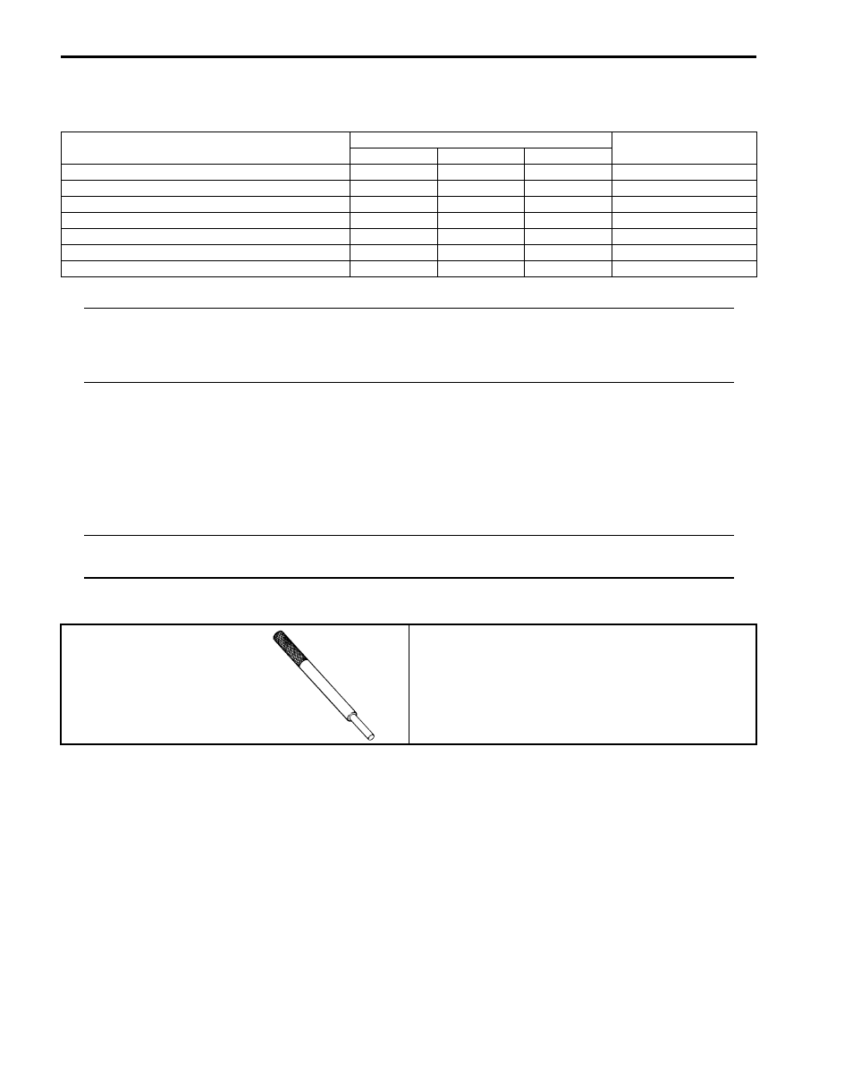
Special Tool
S6JB0B4108002
Fastening part
Tightening torque
Note
N
⋅m
kgf-m
lb-ft
Front brake caliper bleeder plug
7
0.7
5.0
Rear wheel cylinder bleeder plug
7
0.7
5.0
Brake pipe flare nut (M10)
16
1.6
12.0
Brake pipe flare nut (M12)
19
1.9
14.0
Master cylinder fixing nut
18
1.8
13.0
Booster attaching nut
13
1.3
9.5
Clevis pin lock nut
26
2.6
19.0
09916–44310
Valve guide remover (5 mm)
)
Front Brakes: 4B-1
Brakes
Front Brakes
General Description
Front Disc Brake Caliper Assembly Construction
S6JB0B4201001
This caliper is mounted to the brake caliper carrier with two caliper pin bolts. Hydraulic force, created by applying force
to the brake pedal, is converted by the caliper to friction. The hydraulic force acts equally against the piston and the
bottom of the caliper bore to move the piston outward and to move (slide) the caliper inward, resulting in a clamping
action on the disc. This clamping action forces the pads (linings) against the disc, creating friction to stop the vehicle.
For components, refer to “Front Disc Brake Components”.
NOTE
Lubricate parts as specified. Do not use lubricated shop air on brake parts as damage to rubber
components may result. If any component is removed or line disconnected, bleed the brake system.
Replace pads in axle sets only. The torque values specified are for dry, unlubricated fasteners.
4B-2 Front Brakes:
Repair Instructions
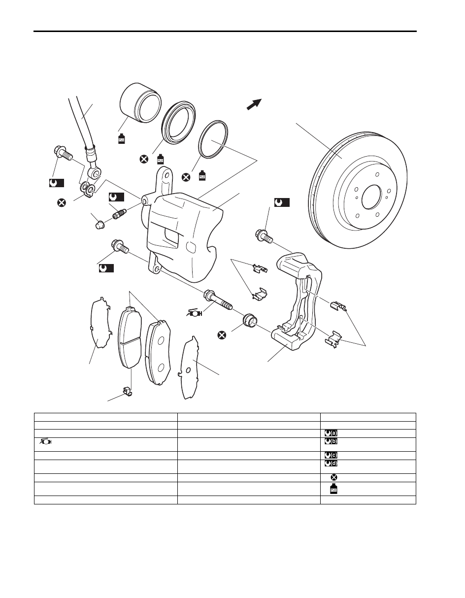
Front Disc Brake Components
S6JB0B4206001
9
16
17
15
14
4
5
7
7
1
2
3
6
8
8
10
11
12
13
18
19
(b)
(a)
(c)
(d)
F
I6JB0B420001-01
1. Caliper
10. Piston seal
19. Brake disc
2. Caliper pin bolt
11. Piston boot
F: Forward
3. Slide pin boot
12. Brake caliper carrier
: 36 N
⋅m (3.6 kgf-m, 26.0 lb-ft)
4. Slide pin
: Use included grease for pin boot.
13. Caliper carrier bolt
: 85 N
⋅m (8.5 kgf-m, 61.5 lb-ft)
5. Brake pad
14. Front caliper bleeder plug
: 7 N
⋅m (0.7 kgf-m, 5.0 lb-ft)
6. Wear indicator (vehicle center side on right wheel
brake only)
15. Bleeder plug cap
: 23 N
⋅m (2.3 kgf-m, 17.0 lb-ft)
7. Shim
16. Brake flexible hose
: Do not reuse.
8. Pad spring
17. Flexible hose joint bolt
: Apply brake fluid
9. Disk brake piston
18. Hose washer
Front Brakes: 4B-3
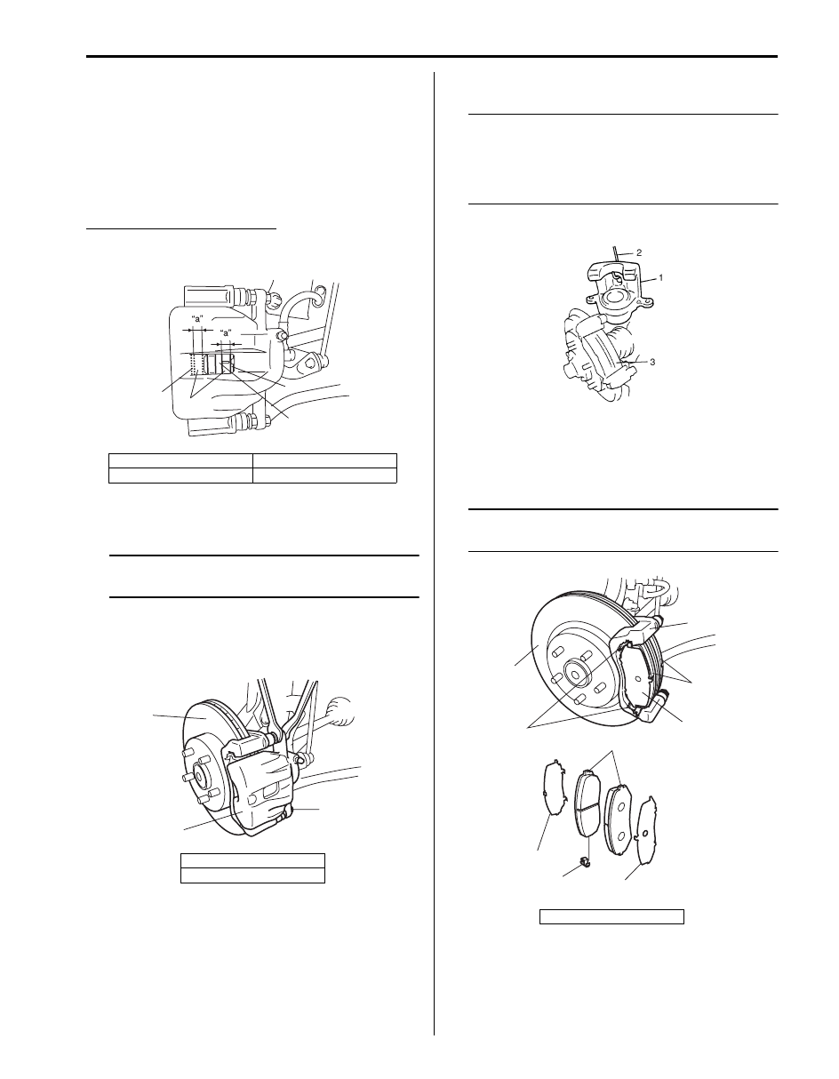
Front Disc Brake Pad On-Vehicle Check
S6JB0B4206002
Inspect pad linings periodically according to
maintenance schedule whenever wheels are removed
(for tire rotation or other reason). Take a look through
hole of caliper and check lining thickness of outside and
inside pads.
If one of brake pad is worn to service limit, all linings
must be replaced at the same time.
Front brake pad thickness “a”
Standard: 11.0 mm (0.43 in.)
Limit: 2.0 mm (0.08 in.)
Front Disc Brake Pad Removal and Installation
S6JB0B4206003
NOTE
When replacing brake pad, replace it on the
right and left.
Removal
1) Hoist vehicle and remove front wheel.
2) Remove caliper pin bolts (2).
3) Remove caliper (1) from caliper carrier.
NOTE
Hang removed caliper (1) with a wire hook (2)
or the like so as to prevent brake hose from
bending and twisting excessively or being
pulled. Don’t operate brake pedal with pads
removed.
4) Remove pads (3).
Installation
1) Install pad spring (1), shims (6) and pads (2) to
caliper carrier (4).
NOTE
Install brake pad with wear indicator (5) to
vehicle center side on right wheel brake.
1. Pad rim
3. Disc
2. Lining
1. Caliper
3. Disc
3
1
1
2
I5JB0A420002-01
3
1
2
I5JB0A420003-01
3. Disc
I1SQ01420004-01
5
2
2
1
3
4
6
6
6
I5JB0A420004-01
Нет комментариевНе стесняйтесь поделиться с нами вашим ценным мнением.
Текст