Suzuki Grand Vitara JB627. Service manual — part 85
1D-21 Engine Mechanical:
• Use new exhaust manifold gasket.
• Tighten exhaust manifold mounting bolts and nuts to
specified torque referring to “Exhaust Manifold
Removal and Installation in Section 1K”.
• Refill coolant referring to “Cooling System Flush and
• Finally, start engine and check for engine coolant
leaks and exhaust gas leakage.
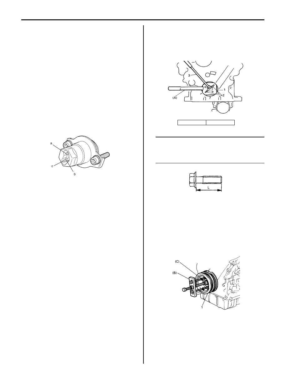
Engine Block Heater (If Equipped) Inspection
S6JB0B1406015
• Check continuity between terminal “a” and “c”. If there
is no continuity, replace it.
• Check that there is no continuity between terminal “a”
or “b” and “c”. If there is continuity, replace it.
• Check continuity between terminal “c” and engine
block heater body. If there is no continuity, replace it.
Timing Chain Cover Removal and Installation
S6JB0B1406016
Removal
1) Remove engine assembly from vehicle. Refer to
“Engine Assembly Removal and Installation”.
2) Remove electric throttle body assembly with intake
collector and intake manifold. Refer to “Intake
Collector and Intake Manifold Removal and
Installation” and “Electric Throttle Body Assembly
Removal and Installation”.
3) Remove cylinder head covers. Refer to “Cylinder
Head Covers Removal and Installation”.
4) Remove P/S pump and A/C compressor (if
equipped) drive belt referring to “P/S Pump and A/C
Compressor (If Equipped) Drive Belt Removal and
Installation in Section 6C”.
5) Remove water pump and generator drive belt. Refer
to “Water Pump and Generator Drive Belt Removal
and Installation in Section 1J”.
6) Remove water pump pulley.
7) Remove thermostat cap. Refer to “Thermostat
Removal and Installation in Section 1F”.
8) Remove P/S pump bracket. Refer to “P/S Hose /
Pipe Components in Section 6C”.
9) Remove oil pans. Refer to “Oil Pan and Oil Pump
Strainer Removal and Installation in Section 1E”.
10) Remove crankshaft pulley bolt (1). To lock crankshaft
pulley, use special tool (camshaft pulley holder) as
shown in figure.
Special tool
(A): 09917–68221
NOTE
Be sure to use the following bolt for fixing
special tool to crankshaft pulley.
Bolt size: M8, P1.25 L=45 mm
Strength: 7T
11) Remove crankshaft pulley (1).
If it is hard to remove, use special tools (Steering
wheel remover, Bearing puller attachment) as shown
in figure.
If bolts of steering wheel remover are too long,
replace them with those of suitable length.
Special tool
(A): 09944–36011
(B): 09926–58010
12) Remove timing chain cover.
I1SQ01162003-01
2. Bolt
3. Wrench
IYSQ01143031-01
IYSQ01143032-01
I6JB01140038-01
Engine Mechanical: 1D-22
Installation
Reverse removal sequence to install timing chain cover
noting the following points.
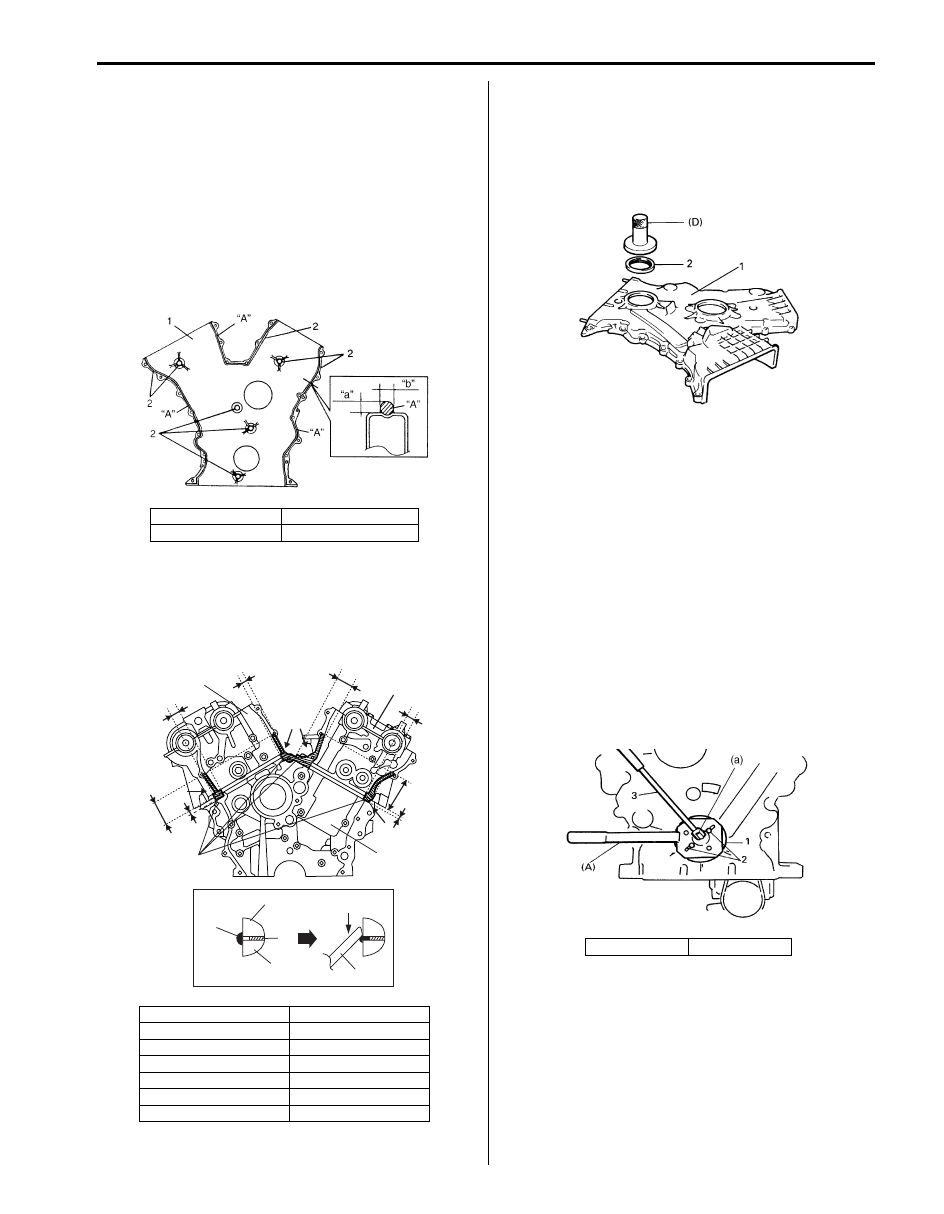
• Clean sealing surface on timing chain cover,
crankcase, cylinder block and cylinder heads.
Remove oil, old sealant, and dust from sealing
surface.
• Apply sealant “A” to timing chain cover sealing
surface area as shown in figure.
“A”: Sealant 99000–31260 (SUZUKI Bond
No.1217G)
• Apply sealant “B” to mating surfaces of cylinder head
and cylinder block as shown in figure.
“B”: Water tight sealant 99000–31140 (SUZUKI
Bond No.1207B)
• Apply engine oil to new oil seal lip and water pump O-
ring. Using special tool (bearing installer), install new
oil seal (2) with its surface is flash with edge of timing
chain cover (1).
Special tool
(D): 09913–75510
• Install timing chain cover.
Tightening torque
Timing chain cover bolt: 11 N·m (1.1 kgf-m, 8.0 lb-
ft)
• Install CMP sensor to timing chain cover referring to
“Camshaft Position (CMP) Sensor Removal and
Installation in Section 1C”.
• Install crankshaft pulley (1).
To lock crankshaft pulley, use special tool (camshaft
pulley holder) with it at shown in figure.
Special tool
(A): 09917–68221
Tightening torque
Crankshaft pulley bolt (a): 150 N·m (15 kgf-m,
108.5 lb-ft)
“a”: 2 mm (0.08 in.)
1. Timing chain cover
“b”: 3 mm (0.11 in)
2. Sealant “A”
[A]: View A
“a”: 7 mm (0.28 in.)
1. Cylinder head
“b”: 67 mm (2.64 in.)
2. Cylinder block
“c”: 17 mm (0.67 in.)
3. Cylinder head gasket
“d”: 18 mm (0.71 in.)
4. Rub into
“e”: 10 mm (0.39 in.)
5. Jig
“f”: 34 mm (1.34 in.)
“g”: 50 mm (1.97 in)
I6JB01140114-01
"a"
"b"
"d"
"f"
"e"
"c"
"a"
"g"
2
"B"
1
1
A
A
A
[A]
"B"
1
3
2
4
5
I5JA01140005-02
2. Bolt
3. Wrench
IYSQ01143037-01
I6JB01140108-01
1D-23 Engine Mechanical:
NOTE
Be sure to use the following bolt for fixing
special tool to crank pulley.
Bolt size: M8, P1.25 L=45 mm
Strength: 7T
Timing Chain Cover Inspection
S6JB0B1406017
Check oil seal lip for damage or deterioration. Replace
as necessary.
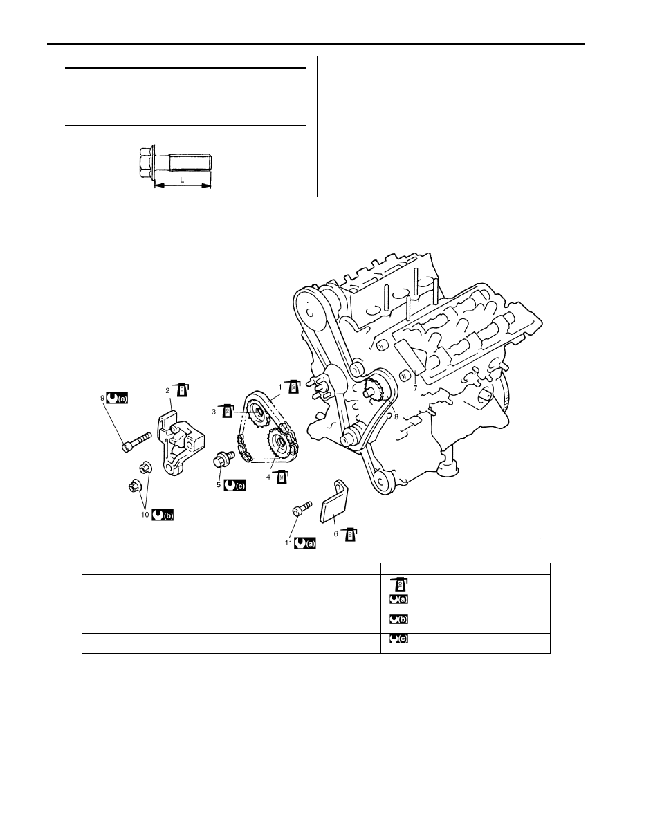
LH (No.1) Bank 2nd Timing Chain and Chain Tensioner Components
S6JB0B1406018
IYSQ01143032-01
I6JB01140039-01
1. LH (No.1) bank 2nd timing chain
6. Timing chain guide No.4
11. Timing chain guide No. 4 bolt
2. Timing chain tensioner adjuster No.3
7. Timing chain guide No.5
: Apply engine oil to sliding surface of
each point.
3. LH (No.1) bank intake camshaft
sprocket
8. Idler sprocket No.2
: 11 N
⋅m (1.1 kgf-m, 8.0 lb-ft)
4. LH (No.1) bank exhaust camshaft
sprocket
9. Timing chain tensioner adjuster No. 3 bolt
: Tighten 45 N
⋅m (4.5 kgf-m, 32.5 lb-ft) by
the specified procedure.
5. Camshaft sprocket bolt
10. Timing chain tensioner adjuster No. 3 nut
: Tighten 80 N
⋅m (8.0 kgf-m, 58.0 lb-ft) by
the specified procedure.
Engine Mechanical: 1D-24
LH (No.1) Bank 2nd Timing Chain and Chain
Tensioner Removal and Installation
S6JB0B1406019
Removal
1) Remove engine assembly from vehicle. Refer to
“Engine Assembly Removal and Installation”.
2) Remove timing chain cover. Refer to “Timing Chain
Cover Removal and Installation”.
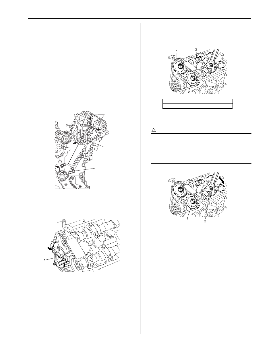
3) Turn crankshaft to meet the following condition.
• Key (1) on crankshaft positions as shown.
• Mark on idler sprocket No.2 (2) points the center
of crankshaft.
• The marks on sprockets (3) match with marks on
cylinder head.
4) Remove timing chain tensioner adjuster No.3 (1).
To remove it, slacken LH (No.1) bank 2nd timing
chain by turning intake camshaft (2)
counterclockwise a little while pushing back pad.
5) Remove LH (No.1) bank intake and exhaust
camshaft sprocket bolts.
To remove it, fit a spanner to hexagonal part (3) at
the center of camshaft to hold it stationary.
6) Remove LH (No.1) bank exhaust camshaft sprocket
(1).
CAUTION
!
Removing sprocket (1) from camshaft (2) may
cause cam to turn, resulting in damage to
valve and piston. To prevent this, when
removing sprocket, hold camshaft stationary
by using a spanner at its hexagonal part.
7) Remove LH (No.1) bank intake camshaft sprocket.
8) Remove LH (No.1) bank 2nd timing chain.
1
2
3
I6JB01140040-01
I6JB01140041-01
1. LH (No.1) bank intake camshaft sprocket
2. LH (No.1) bank exhaust camshaft sprocket
I6JB01140042-01
I6JB01140043-01
Нет комментариевНе стесняйтесь поделиться с нами вашим ценным мнением.
Текст