Suzuki Grand Vitara JB627. Service manual — part 32
1A-77 Engine General Information and Diagnosis:
DTC P0102 / P0103: Mass Air Flow Circuit Low / High Input
S6JB0B1104019
Wiring Diagram
Refer to “DTC P0101: Mass Air Flow Circuit Range / Performance”.
DTC Detecting Condition and Trouble Area
DTC Confirmation Procedure
1) With ignition switch OFF, connect scan tool.
2) Turn ON ignition switch and clear DTC by using scan tool if any.
3) Start engine and run it for 10 sec.
4) Check DTC by using scan tool.
DTC Troubleshooting
DTC detecting condition
Trouble area
DTC P0102: Mass Air Flow Circuit Low Input
Output voltage of MAF sensor is less than 0.3 V for 1 second or longer.
(1 driving cycle detection logic)
• MAF sensor and its circuit
• ECM
DTC P0103: Mass Air Flow Circuit High Input
Output voltage of MAF sensor is more than 0.5 V for 1 second or longer.
(1 driving cycle detection logic)
Step
Action
Yes
No
1
Was “Engine and Emission Control System Check”
performed?
Go to Step 2.
Go to “Engine and
Emission Control
System Check”.
2
MAF sensor and its circuit check
1) Connect scan tool to DLC with ignition switch turned
OFF.
2) Start engine and check MAF value displayed on scan
tool. (Refer to “Scan Tool Data” for normal value.)
Is normal value indicated?
Intermittent trouble.
Check for intermittent
referring to “Intermittent
and Poor Connection
Inspection in Section
00”.
Go to Step 3.
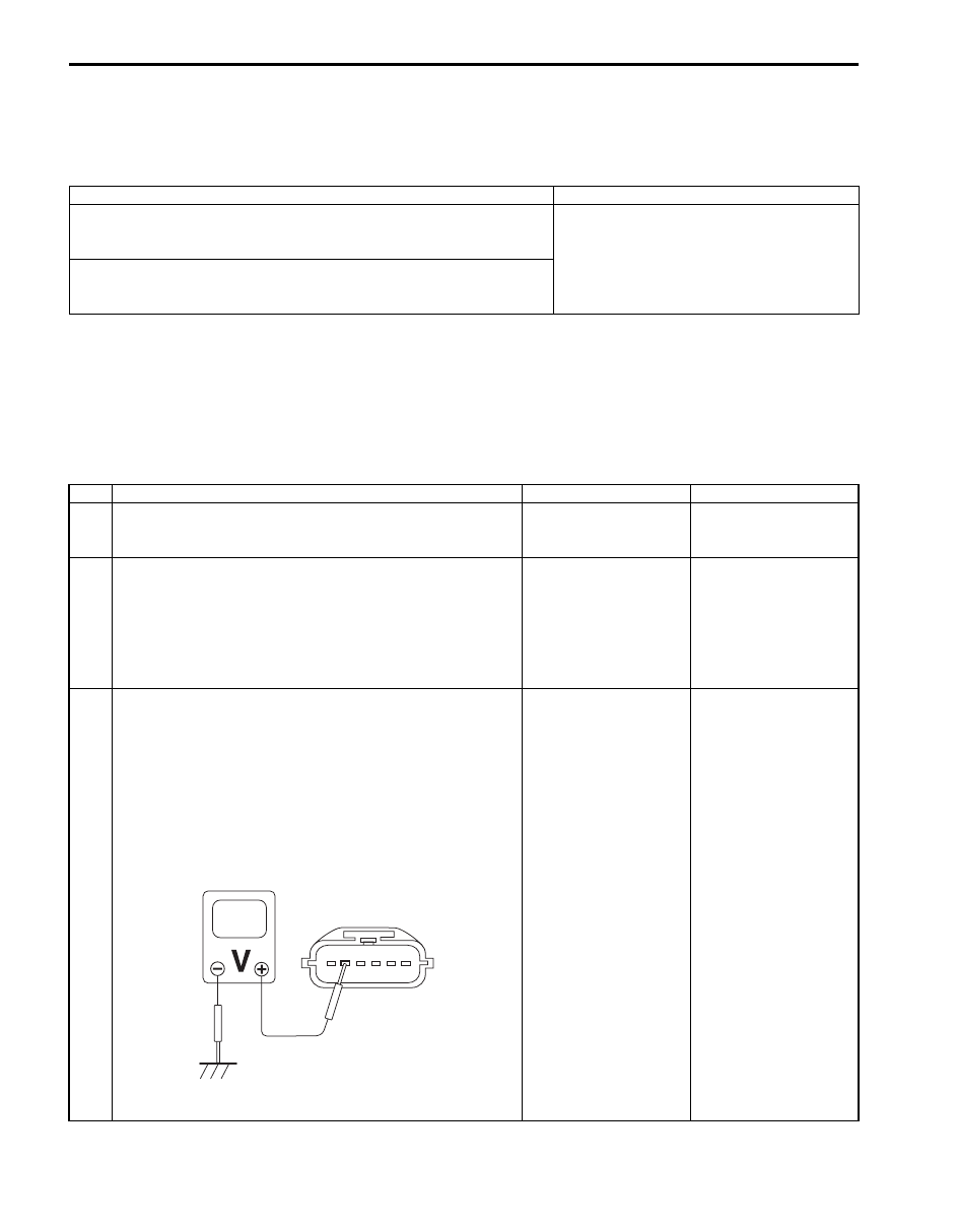
3
MAF sensor power supply voltage check
1) Disconnect connector from MAF sensor with ignition
switch turned OFF.
2) Check for proper terminal connection to MAF sensor and
ECM connectors
3) If connections are OK, turn ignition switch to ON
position.
4) Check that MAF sensor power supply voltage is battery
voltage.
Is it in good condition?
Go to Step 4.
Repair or replace MAF
sensor power supply
circuit.
I6JB01110028-01
Engine General Information and Diagnosis: 1A-78
DTC P0107 / P0108: Manifold Absolute Pressure Sensor Circuit Low / High Input
S6JB0B1104020
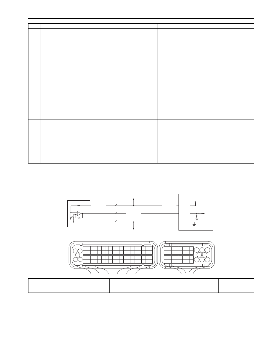
Wiring Diagram
4
Wire harness check
1) Turn ignition switch OFF position.
2) Disconnect connector from ECM.
3) Check that MAF sensor circuit is as follows.
• Wiring harness resistance of each MAF sensor signal
circuit and ground circuit is less than 3
Ω.
• Insulation resistance between MAF sensor signal
circuit and vehicle body ground is Infinity.
• Insulation resistance of wire harness is infinity
between MAF sensor signal terminal and each other
terminal at MAF and IAT sensor connector.
• Circuit voltage of each MAF sensor signal circuit and
ground circuit is 0 – 1 V with ignition switch turned
ON.
Are they in good condition?
Go to Step 5.
Repair or replace
defective wire harness.
5
MAF sensor signal check
1) Turn ignition switch OFF position.
2) Connect connectors to MAF sensor and ECM.
3) Check MAF sensor signal voltage referring to “Mass Air
Flow (MAF) and Intake Air Temperature (IAT) Sensor
On-Vehicle Inspection in Section 1C”.
Is each value within specified range?
Substitute a known
good ECM and recheck.
Replace MAF and IAT
sensor.
Step
Action
Yes
No
1
3 2
4
5
6
7
8
9
1110
12
13
14
15
16
17
18
19
20
17
18
19
20
21
22
23
24
25
26
27
28
29
30
31
33
34
35
36
37
38
39
40
32
1
2
3
4
5
6
7
8
9
10
11
12
13
14
15
16
21
22
23
24
25
26
27
28
29
30
31
32
33
34
35
36
37
38
39
40
41
42
43
44
45
46
47
48
49
50
51
52
53
54
55
56
57
58
59
60
61
62
63
64
65
66
67
68
69
70
71
72
73
74
75
76
77
78
79
80
81
E23
C37
4
1
2
3
GRY/RED
5V
C37-49
C37-68
RED/WHT
GRY/GRN
GRY/RED
GRY/GRN
C37-67
P
S
G
I6JB01110029-02
P: MAP sensor power supply circuit
1. Manifold absolute pressure sensor
4. ECM
S: MAP sensor signal circuit
2. To A/C refrigerant pressure sensor (if equipped with A/C)
G: MAP sensor ground circuit
3. To other sensors

1A-79 Engine General Information and Diagnosis:
DTC Detecting Condition and Trouble Area
DTC Confirmation Procedure
WARNING
!
• When performing a road test, select a place where there is no traffic or possibility of a traffic
accident and very careful during testing to avoid occurrence of an accident.
• Road test should be carried out with 2 persons, a driver and a tester, on a level road.
1) With ignition switch OFF, connect scan tool.
2) Turn ON ignition switch and clear DTC by using scan tool if any.
3) Run engine at idle speed for 1 minute.
4) Check DTC and pending DTC by using scan tool.
DTC Troubleshooting
NOTE
Before this trouble shooting is performed, read the precautions for DTC troubleshooting referring to
“Precautions for DTC Troubleshooting”.
DTC detecting condition
Trouble area
DTC P0107: Manifold Absolute Pressure Sensor Circuit Low Input
Output voltage of MAP sensor is less than 0.1 V for 2.6 seconds or longer.
(1 driving cycle detection logic)
• MAP sensor and its circuit
• ECM
DTC P0108: Manifold Absolute Pressure Sensor Circuit High Input
Output voltage of MAP sensor is more than 4.9 V for 2.6 seconds or
longer.
(1 driving cycle detection logic)
Step
Action
Yes
No
1
Was “Engine and Emission Control System Check”
performed?
Go to Step 2.
Go to “Engine and
Emission Control
System Check”.
2
MAP sensor and its circuit check
1) Connect scan tool to DLC with ignition switch OFF.
2) Turn ignition switch ON.
3) Check intake manifold pressure.
Is it 0 kPa or 126 kPa?
Go to Step 3.
Intermittent trouble. If
OK, substitute a known
good ECM and recheck.

Engine General Information and Diagnosis: 1A-80
3
Wire harness check
1) Turn ignition switch OFF position.
2) Disconnect connectors from MAP sensor and ECM.
3) Check for proper terminal connection to MAP sensor
and ECM connectors.
4) If connections are OK, check that MAP sensor circuit is
as follows.
• Wiring harness resistance of each MAP sensor power
supply, signal and ground circuit is less than 3
Ω.
• Insulation resistance of each MAP sensor power
supply and signal circuit is infinity between MAP
sensor connector and vehicle body ground.
• Insulation resistance of wire harness is infinity
between MAP sensor signal terminal and each other
terminal at MAP sensor connector.
• Circuit voltage of each MAP sensor power supply,
signal and ground circuit is 0 – 1 V with ignition switch
turned ON.
Are they in good condition?
Go to Step 4.
Repair or replace
defective wire harness.
4
Wire harness check
1) Connect connectors to ECM.
2) Turn ignition switch to ON position.
3) Check that MAP sensor power supply voltage is 5 V
between power supply terminal and ground terminal of
MAP sensor connector.
Is it in good condition?
Go to Step 5.
Go to Step 6.
5
MAP sensor check
1) Check MAP sensor, referring to “Manifold Absolute
Pressure (MAP) Sensor Inspection in Section 1C”.
Is it in good condition?
Substitute a known
good ECM and recheck.
Replace MAP sensor.
6
Wire harness check
1) Turn ignition switch OFF position.
2) Disconnect connector from A/C refrigerant pressure
sensor.
3) Turn ignition switch to ON position.
4) Check that MAP sensor power supply voltage is 5 V
between power supply terminal and ground terminal of
MAP sensor connector.
Is it in good condition?
Check A/C refrigerant
pressure sensor and its
circuit.
Substitute a known-
good ECM and recheck.
Step
Action
Yes
No
Нет комментариевНе стесняйтесь поделиться с нами вашим ценным мнением.
Текст