Suzuki Grand Vitara JB627. Service manual — part 267
7-1 Precautions:
HVAC
Precautions
Precautions
Precautions for HVAC
S6JB0B7000001
Air Bag Warning
Refer to “Air Bag Warning in Section 00”.
A/C System Caution
Refer to “A/C System Caution in Section 00”.
Precautions on Servicing A/C System
Refer to “Precautions on Servicing A/C System in Section 7B”.
Precautions on Servicing Compressor
Refer to “Precautions on Replenishing Compressor Oil in Section 7B”.
Heater and Ventilation: 7A-1
HVAC
Heater and Ventilation
General Description
Heater and Ventilation Construction
S6JB0B7101001
The heater, an in and out air selectable-type hot water heater, is so constructed that it is possible to assure an
agreeable ventilation at all times by providing the ventilator air outlets at the center and both sides (right and left) of the
instrument panel, the hot air outlet at a place close to the feet of front passengers, and the defroster air outlets at
places, right and left, along the windshield glass.
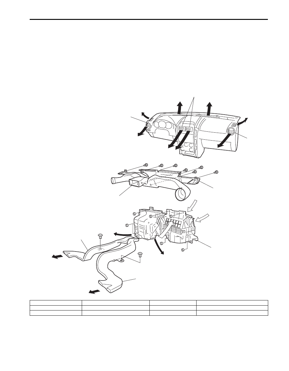
The heater and ventilation consist of the following parts.
7
7
2
2
5
5
6
6
6
6
9
9
8
8
12
3
4
10
11
11
7
7
1
I5JB0A710001-04
1. HVAC unit
4. Defroster duct
7. Foot air
10. Fresh air
2. Rear duct
5. Side ventilation louver
8. Defroster air
11. Recirculation air
3. Ventilator duct
6. Ventilation air
9. Demister air
12. Center ventilation louver
7A-2 Heater and Ventilation:
Body Ventilation Construction
S6JB0B7101002
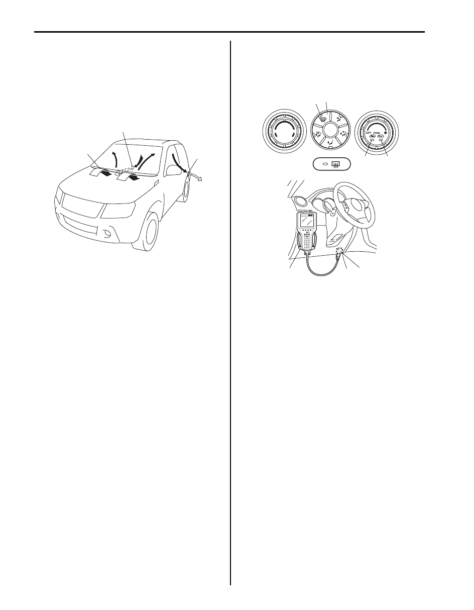
The body ventilation system of this vehicle has a fresh
air intake (1) located at the cowl top panel. When fresh
air intake air selector is at FRE position (fresh),
ventilating air is drawn into the interior from the cowl
center garnish and drawn out from the ventilator outlet
(2) provided at each side body outer panel (both right
and left side).
On-Board Diagnostic System Description (for
Vehicle without A/C)
S6JB0B7101003
HVAC control module (for vehicle without A/C) detects
malfunction, which may occur in the following area.
When HVAC control module detects any malfunction, the
REC (recirculation) indicator light (4) flashes on and off
continuously after turning ignition switch to ON position.
• ECT sensor
• CMP sensor
• Wheel speed sensor
• Temperature control actuator
• Air flow control actuator
• Air intake control actuator
• Temperature selector of HVAC control module
• Blower speed selector of HVAC control module
• Serial communication line
• CAN communication line
DTC can be checked by either one of the following ways.
• DTC can be checked by using SUZUKI scan tool (2)
connected to DLC (1).
• Without using SUZUKI scan tool, DTC can be
checked by reading the flashing pattern of both the
FRE (fresh) indicator light (3) and the REC
(recirculation) indicator light (4).
• Pressing DEF (defogger) switch (5) alternates display
of current DTC and history DTC.
• DEF indicator light (6) remains off when display is in
current DTC and it lights up when display is in history
DTC.
HVAC Control System Description (for Vehicle
without A/C)
S6JB0B7101004
For CAN communication system, refer to description on
“CAN Communication System Description in Section
1A”.
When following data are sent from control modules to
BCM through CAN communication, they are sent from
BCM to HVAC control module through serial
communication line.
• Engine coolant temperature
• Engine Speed
• Wheel speed (Vehicle speed)
HVAC control module has a function to make initial
settings of temperature control actuator, air intake
actuator and air flow actuator.
For vehicle without A/C, HVAC control module uses
engine speed signal so that temperature control
actuator, air intake actuator and air flow actuator can
make initial setting for door position.
Initial settings of actuators are automatically made when
engine is started for the first time after battery is
connected.
When initial settings are made, each actuator is forced to
operate for about 15 seconds continuously.
2
1
2
I5JB0A710002-03
3
4
5
6
1
2
I5JB0A710004-04
Heater and Ventilation: 7A-3
Schematic and Routing Diagram
Heater and Ventilation Wiring Circuit Diagram
S6JB0B7102001
Refer to “A/C System Wiring Circuit Diagram in Section 7B”.
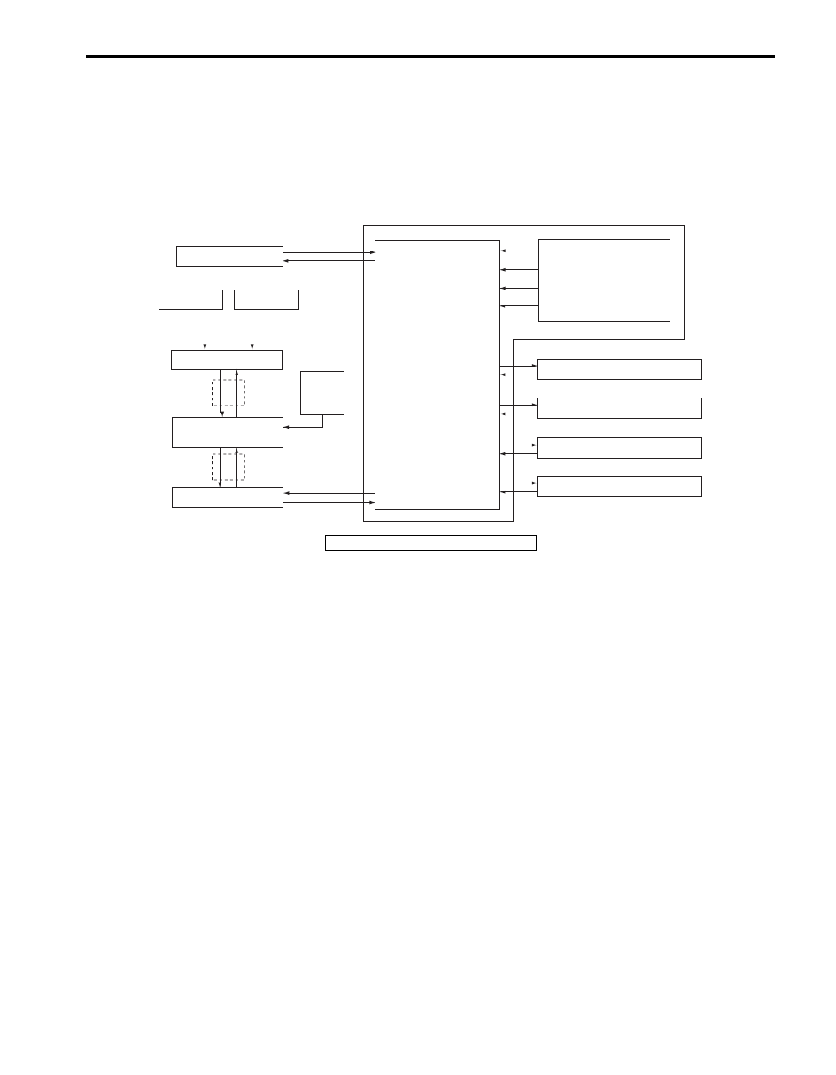
Electronic Control Input / Output Diagram (for Vehicle without A/C)
S6JB0B7102002
Temperature selector
MODE (air flow) selector
Blower speed selector
Air intake selector
Wheel
speed
sensor
Blower motor controller
Temperature control actuator
Air flow control actuator
Air intake control actuator
BCM
ABS control module or
ESP® control module
Data link connector
HVAC control module
CPU
ECT sensor
ECM
CMP sensor
*
*
I6JB01710001-04
*: CAN communication
Нет комментариевНе стесняйтесь поделиться с нами вашим ценным мнением.
Текст