Suzuki Grand Vitara JB627. Service manual — part 384
9D-3 Wipers / Washers:
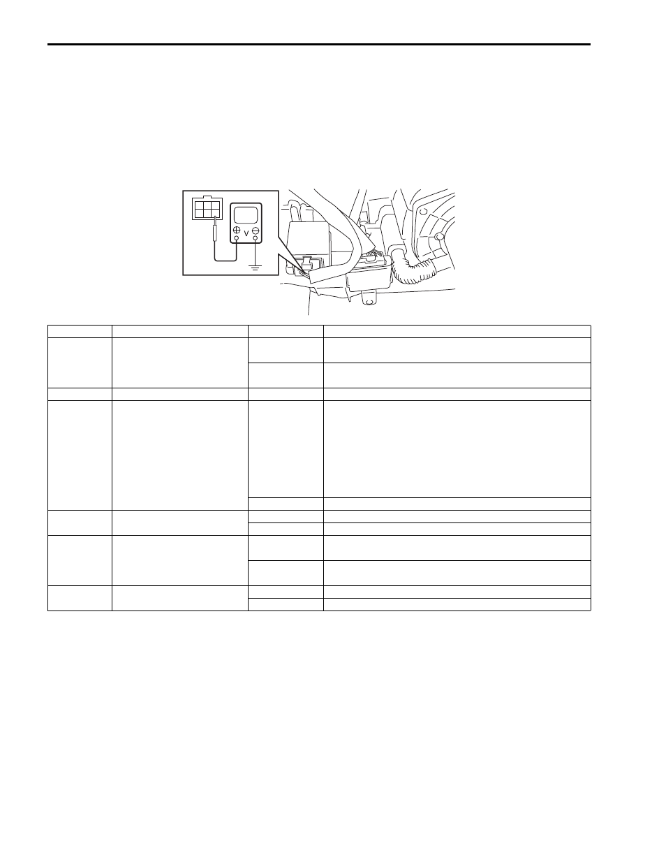
Inspection of Headlight Washer Control Module and Its Circuit (If Equipped)
S6JB0B9404005
1) Remove headlight washer control module from blower unit.
2) Connect connector to headlight washer control module.
3) Check that the voltage between the following terminals and vehicle body ground are specifications under each
condition.
If measuring voltage is not within specification, first check related switch and applicable wire harness circuit for
open or short. And if all wire harness circuits and connections are normal, replace headlight washer control
module.
1
2
3
4
5
6
I5JB0A940001-01
Terminal
Circuit
Specification
Condition
1
To headlight washer switch
0 – 1 V
Ignition switch is at ON position, lighting switch is at
HEAD position and headlight washer switch is pushed.
4 – 6 V
Ignition switch is at ON position and headlight washer
switch is not pushed.
2
Ground
0 – 1 V
—
3
To headlight washer motor
0 – 1 V
When headlight washer pump is in operation.
The headlight washer pump works for 0.8 seconds in
case that the following conditions are all satisfied.
• Ignition switch is at ON position
• Lighting switch is at HEAD position
• Windshield washer switch is at ON position or
headlight washer switch is pushed
10 – 14 V
When headlight washer pump is not in operation.
4
To lighting switch
0 – 1 V
Lighting switch is at HEAD position.
10 – 14 V
Lighting switch is at OFF position.
5
To windshield washer switch
0 – 1 V
Ignition switch is at ON position and windshield washer
switch is at ON position.
10 – 14 V
Ignition switch is at ON position and windshield washer
switch is at OFF position.
6
To ignition switch
0 – 1 V
Ignition switch is at OFF position.
10 – 14 V
Ignition switch is at ON position.
Wipers / Washers: 9D-4
Repair Instructions
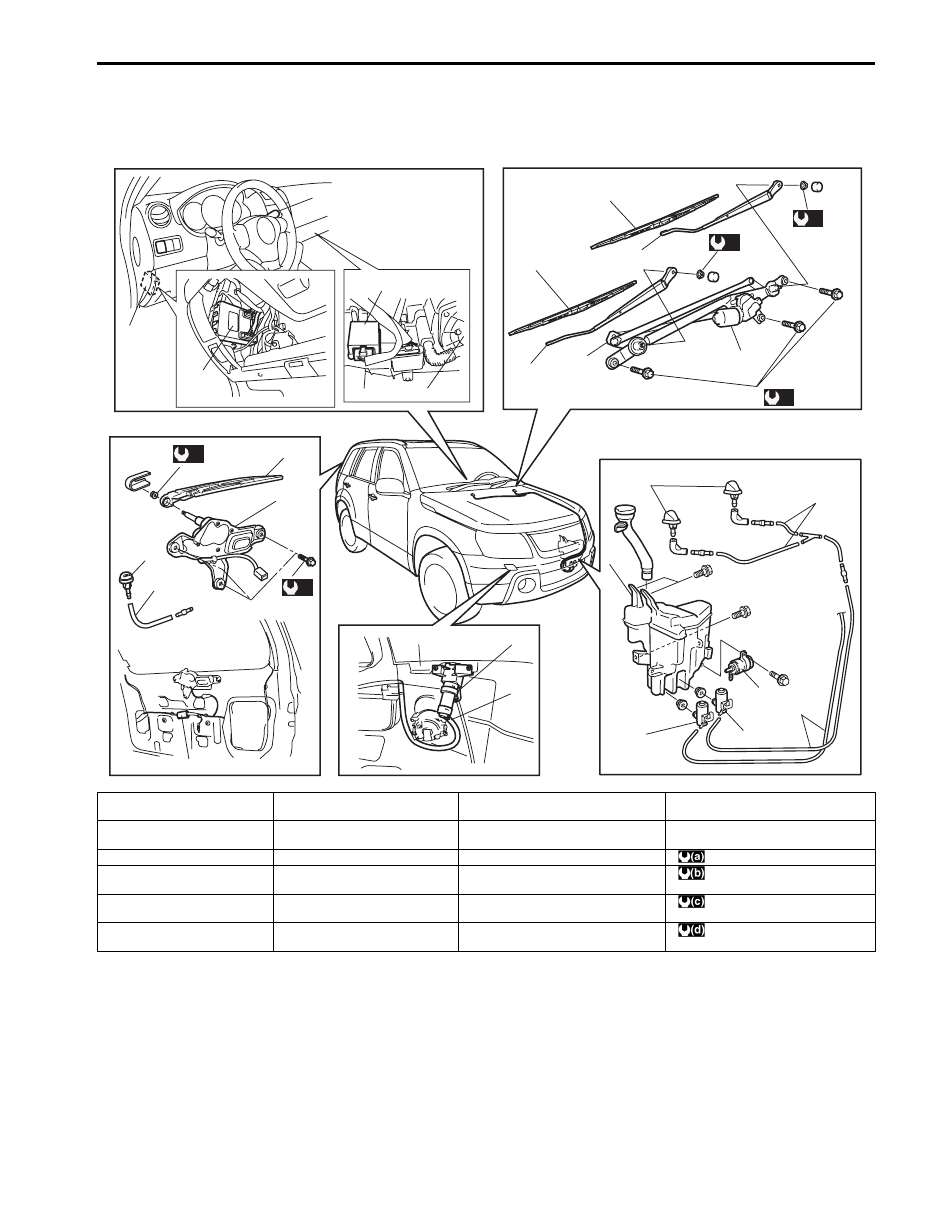
Wipers and Washers Components
S6JB0B9406001
(c)
(d)
11
10
5
6
13
16
10
(a)
(a)
1
2
2
4
3
(b)
15
11
9
7
8
10
10
20
1
14
12
14
18
19
17
I6JB0B940001-01
1. Windshield wiper blade
7. Washer pump for windshield
washer
13. Rear wiper relay
19. Blower fan motor
2. Windshield wiper arm
8. Washer pump for rear washer
14. BCM
20. Headlight washer pump
(if equipped)
3. Windshield wiper motor
9. Washer tank
15. Windshield wiper bolt
: 14 N
⋅m (1.4 kgf-m, 10.5 lb-ft)
4. Windshield wiper link
10. Washer hose
16. Headlight washer nozzle (if
equipped)
: 8.5 N
⋅m (0.85 kgf-m, 6.5 lb-ft)
5. Rear wiper arm with blade
assembly
11. Washer nozzle
17. Front bumper
: 7 N
⋅m (0.7 kgf-m, 5.0 lb-ft)
6. Rear wiper motor
12. Wiper switch
18. Headlight washer control module (if
equipped)
: 8 N
⋅m (0.8 kgf-m, 6.0 lb-ft)
9D-5 Wipers / Washers:
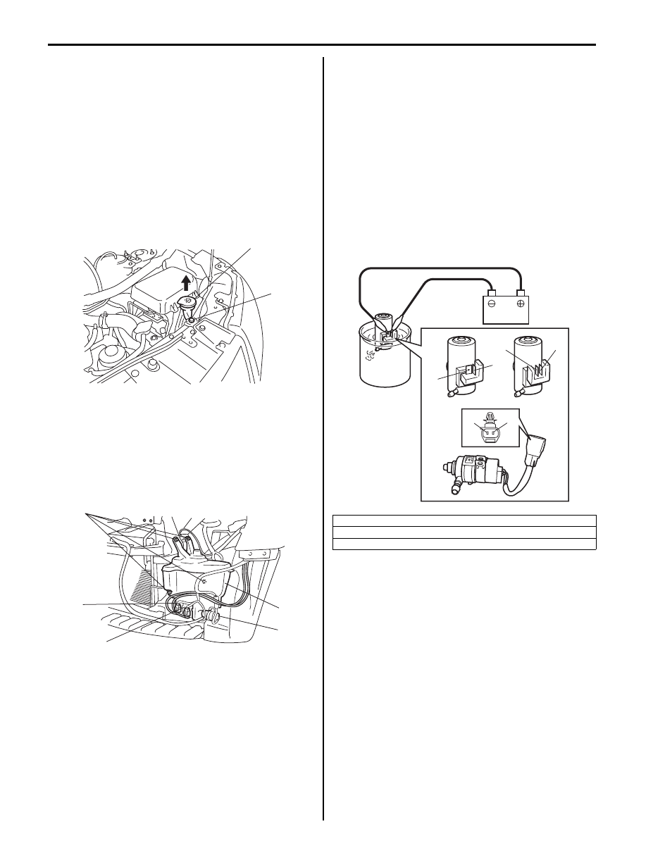
Washer Tank and Washer Pump Removal and
Installation
S6JB0B9406002
Removal
1) Disconnect negative (–) cable at battery.
2) Remove front bumper referring to “Front Bumper
3) Remove right headlight housing from vehicle body
referring to “Headlight Housing Removal and
Installation in Section 9B”.
4) Remove grommet (1) and upper part (2) of washer
tank.
5) Remove washer tank attaching bolts (4).
6) Disconnect washer pump lead wire couplers and
hoses.
7) Remove washer tank (1).
8) Remove windshield washer pump (2), rear washer
pump (3) and headlight washer pump (5) (if
equipped) from washer tank (1).
Installation
Install washer tank and washer pump by reversing
removal procedure, noting the following instructions.
• Connect washer pump connector(s) securely.
• After installing headlight housing be sure to inspect
and adjust aiming referring to “Headlight Aiming
Adjustment with Screen in Section 9B”.
Washer Pump Inspection
S6JB0B9406003
1) Connect battery positive (+) and negative (–)
terminals to pump (+) and (–) terminals respectively.
2) Check front, rear or headlight washer pump for
operation.
If pump does not operate, replace washer pump.
1
2
I5JB0A940003-01
4
3
2
1
5
I5JB0A940005-01
[A]: Windshield washer pump
[B]: Rear washer pump
[C]: Headlight washer pump
(–)
(+)
(–)
(+)
[B]
[A]
[C]
(+)
(–)
I5JB0A940006-01
Wipers / Washers: 9D-6
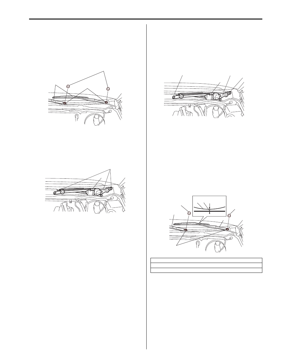
Windshield Wiper Removal and Installation
S6JB0B9406004
Removal
1) Disconnect negative (–) cable at battery.
2) Remove wiper pivot caps (1) and wiper arm nuts (2),
and remove windshield wiper arms with wiper blades
(3).
3) Remove cowl top garnish referring to “Cowl Top
4) Disconnect coupler from windshield wiper motor.
5) Remove bolts (1), and remove windshield wiper
assembly (2).
Installation
1) Install windshield wiper assembly (1), and tighten
bolts (“1” – “3”) according to numerical order as
shown in figure.
Tightening torque
Windshield wiper bolt (a): 8.5 N·m (0.85 kgf-m,
6.5 lb-ft)
2) Connect coupler to windshield wiper motor.
3) Install cowl top garnish referring to “Cowl Top
4) Install windshield wiper arms with wiper blades (1) to
specified position as shown in figure, and then
tighten windshield wiper nuts to specified torque.
Tightening torque
Windshield wiper arm nut (a): 14 N·m (1.4 kgf-
m, 10.5 lb-ft)
5) Install wiper pivot caps (2) to windshield wiper arm
nuts
6) Connect negative (–) cable to battery.
3
2
1
I5JB0A940007-01
2
1
I5JB0A940008-01
“a”: 5 mm (0.20 in.)
3. Ceramic line
4. Wiper blade center
1
(a), “1”
(a), “3”
(a), “2”
I5JB0A940026-01
1
1
(a)
2
2
3
4
“a”
I5JB0A940009-01
Нет комментариевНе стесняйтесь поделиться с нами вашим ценным мнением.
Текст