Suzuki Grand Vitara JB627. Service manual — part 404
9K-9 Body Structure:
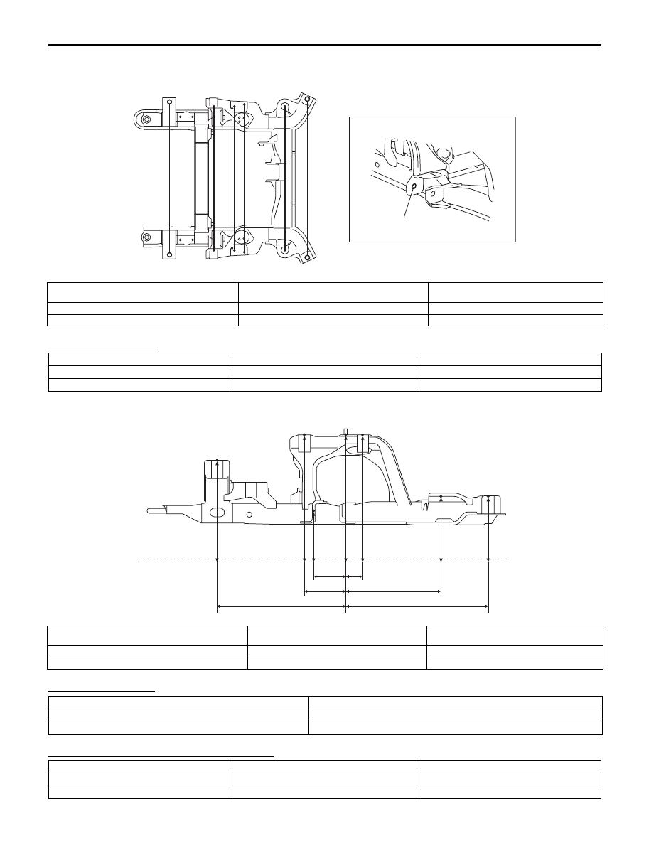
Front Suspension Frame
Hole to hole distance
Hole to hole distance
Projection dimension from standard line “A”
a
b
c
d e
f
g
a'
b'
c'
c'
d' e'
f'
g'
I5JB0A9B0013-01
a (a’). Front suspension frame installation front side
bolt hole
d (d’). Front suspension frame stud
g (g’). Front suspension frame installation rear
side bolt hole
b (b’). Front suspension frame installation bolt hole
e (e’). Front suspension frame installation bolt hole
c (c’). Front suspension arm installation front side hole
f (f’). Front suspension arm installation rear side hole
a-a’: 830 mm (32.68 in.)
d-d’: 790 mm (31.10 in.)
g-g’: 860 mm (33.86 in.)
b-b’: 840 mm (33.07 in.)
e-e’: 794 mm (31.26 in.)
c-c’: 780 mm (30.71 in.)
f-f’: 780 mm (30.71 in.)
a
b
c
d
e
f
g
“A”
I5JB0A9B0014-01
a. Front suspension frame installation front side bolt hole
d. Front suspension frame stud
g. Front suspension frame installation rear side
bolt hole
b. Front suspension frame installation bolt hole
e. Front suspension frame installation bolt hole
c. Front suspension arm installation front side hole
f. Front suspension arm installation rear side hole
a-d: 349 mm (13.74 in.)
d-e: 51 mm (2.01 in.)
b-d: 110 mm (4.33 in.)
d-f: 275 mm (10.83 in.)
c-d: 80 mm (3.15 in.)
d-g: 395 mm (15.55 in.)
a: 193 mm (7.60 in.)
d: 263 mm (10.35 in.)
g: 95 mm (3.74 in.)
b: 263 mm (10.35 in.)
e: 263 mm (10.35 in.)
c: 49 mm (1.93 in.)
f: 96 mm (3.78 in.)
Body Structure: 9K-10
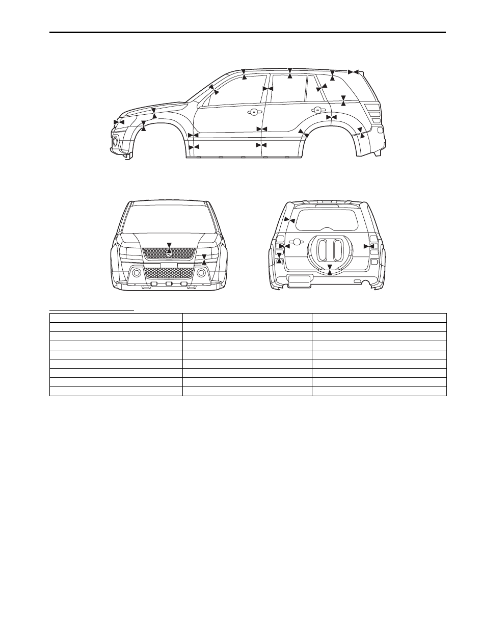
Panel Clearance
S6JB0B9B07002
Panel to panel distance
b
c
f
a
e
d
g
i
j
q
l
m
r
n
o
h
s
p
aa
bb
cc
ee
ff
k
dd
I6JB019B0004-01
a: 7.5 – 9.5 mm (0.296 – 0.374 in.)
j: 4.0 – 6.0 mm (0.158 – 0.236 in.)
s: 16.8 – 18.8 mm (0.662 – 0.740 in.)
b: 1.0 – 3.0 mm (0.040 – 0.118 in.)
k: 3.0 – 5.0 mm (0.119 – 0.196 in.) aa: 4.0 – 6.0 mm (0.158 – 0.236 in.)
c: 1.9 – 3.9 mm (0.075 – 0.153 in.)
l: 3.0 – 5.0 mm (0.119 – 0.196 in.) bb: 6.3 – 8.3 mm (0.249 – 0.327 in.)
d: 0.5 – 1.0 mm (0.020 – 0.039 in.)
m: 4.0 – 6.0 mm (0.158 – 0.236 in.) cc: 5.0 – 7.0 mm (0.197 – 0.275 in.)
e: 7.0 – 9.0 mm (0.275 – 0.354 in.)
n: 3.3 – 5.3 mm (0.120 – 0.208 in.) dd: 6.2 – 8.2 mm (0.245 – 0.322 in.)
f: 3.0 – 5.0 mm (0.119 – 0.196 in.)
o: 1.8 – 3.8 mm (0.071 – 0.149 in.) ee: 4.0 – 6.0 mm (0.158 – 0.236 in.)
g: 4.0 – 6.0 mm (0.158 – 0.236 in.)
p: 0.5 – 1.0 mm (0.020 – 0.039 in.)
ff: 1.0 – 3.0 mm (0.040 – 0.118 in.)
h: 6.0 – 8.0 mm (0.237 – 0.314 in.)
q: 3.0 – 5.0 mm (0.119 – 0.196 in.)
i: 4.0 – 6.0 mm (0.158 – 0.236 in.)
r: 4.0 – 6.0 mm (0.158 – 0.236 in.)
9L-1 Paint / Coatings:
Body, Cab and Accessories
Paint / Coatings
General Description
Anti-Corrosion Treatment Construction
S6JB0B9C01001
WARNING
!
Standard shop practices, particularly eye
protection, should be followed during the
performance of the following operations to
avoid personal injury.
As rust proof treatment, steel sheets are given corrosion
resistance on the interior and/or exterior.
These corrosion resistance steel sheet materials are
called one of two-side galvanized steel sheets.
It is for the sake of rust protection that these materials
are selected and given a variety of treatments as
described blow.
• Steel sheets are treated with cathodic electro primer
which is excellent in corrosion resistance.
• Rust proof wax coatings are applied to door and side
sill insides where moisture is liable to stay.
• Vinyl coating is applied to body underside and wheel
housing inside.
• Sealer is applied to door hem, engine compartment
steel sheet-to-steel sheet joint, and the like portions to
prevent water penetration and resulting in rust
occurrence.
In panel replacement or collision damage repair, leaving
the relevant area untreated as it is in any operation
which does disturb the rust proof treatment will cause
corrosion to that area. Therefore, it is the essential
function of any repair operation to correctly recoat the
related surfaces of the relevant area.
All the metal panels are coated with metal conditioners
and primer coating during vehicle production. Following
the repair and/or replacement parts installation, every
accessible bare metal surface should be cleaned and
coated with rust proof primer. Perform this operation
prior to the application of sealer and rust proof wax
coating.
Sealer is applied to the specific joints of a vehicle during
production. The sealer is intended to prevent dust from
entering the vehicle and serves also as an anticorrosion
barrier. The sealer is applied to the door and hood hem
areas and between panels. Correct and reseal the
originally sealed joints if damaged. Reseal the attaching
joints of a new replacement panel and reseal the hem
area of a replacement door or hood.
Use a quality sealer to seal the flanged joints, overlap
joints and seams. The sealer must have flexible
characteristics and paint ability after it’s applied to repair
areas.
For the sealer to fill open joints, use caulking material.
Select a sealer in conformance with the place and
purpose of a specific use. Observe the manufacturer’s
label-stand instructions when using the sealer.
In many cases, repaired places require color painting.
When this is required, follow the ordinary techniques
specified for the finish preparation, color painting and
undercoating build-up.
Rust proof wax, a penetrative compound, is applied to
the metal-to-metal surfaces (door and side sill insides)
where it is difficult to use ordinary undercoating material
for coating. Therefore, when selecting the rust proof
wax, it may be the penetrative type.
During the undercoating (vinyl coating) application, care
should be taken that sealer is not applied to the engine-
related parts and shock absorber mounting or rotating
parts. Following the under coating, make sure that body
drain holes are kept open.
The sequence of the application steps of the anti-
corrosion materials are as follows:
1) Clean and prepare the metal surface.
2) Apply primer.
3) Apply sealer (all joints sealed originally).
4) Apply color in areas where color is required such as
hem flanges, exposed joints and under body
components.
5) Apply anticorrosion compound (penetrative wax).
6) Apply undercoating (rust proof material).
Paint / Coatings: 9L-2
Plastic Parts Finishing
S6JB0B9C01002
Paintable plastic parts are ABS plastic parts.
Painting
Rigid or hand ABS plastic needs no primer coating.
General acrylic lacquers can be painted properly over
hard ABS plastic in terms of adherence.
1) Use cleaning solvent for paint finish to wash each
part.
2) Apply conventional acrylic color lacquer to part
surface.
3) Follow lacquer directions for required drying time.
(Proper drying temperature range is 60 – 70
°C (140
– 158
°F)).
Reference
Plastic parts employ not only ABS (Acrylonitrile
Butadiene Styrene) plastic but also polypropylene, vinyl,
or the like plastic. Burning test method to identify ABS
plastic is described below.
1) Use a sharp blade to cut off a plastic sliver from the
part at its hidden backside.
2) Hold sliver with pincers and set it on fire.
3) Carefully observe condition of the burning plastic.
4) ABS plastic must raise readily distinguishable back
smoke while burning with its residue suspended in
air temporarily.
5) Polypropylene must raise no readily distinguishable
smoke while burning.
Component Location
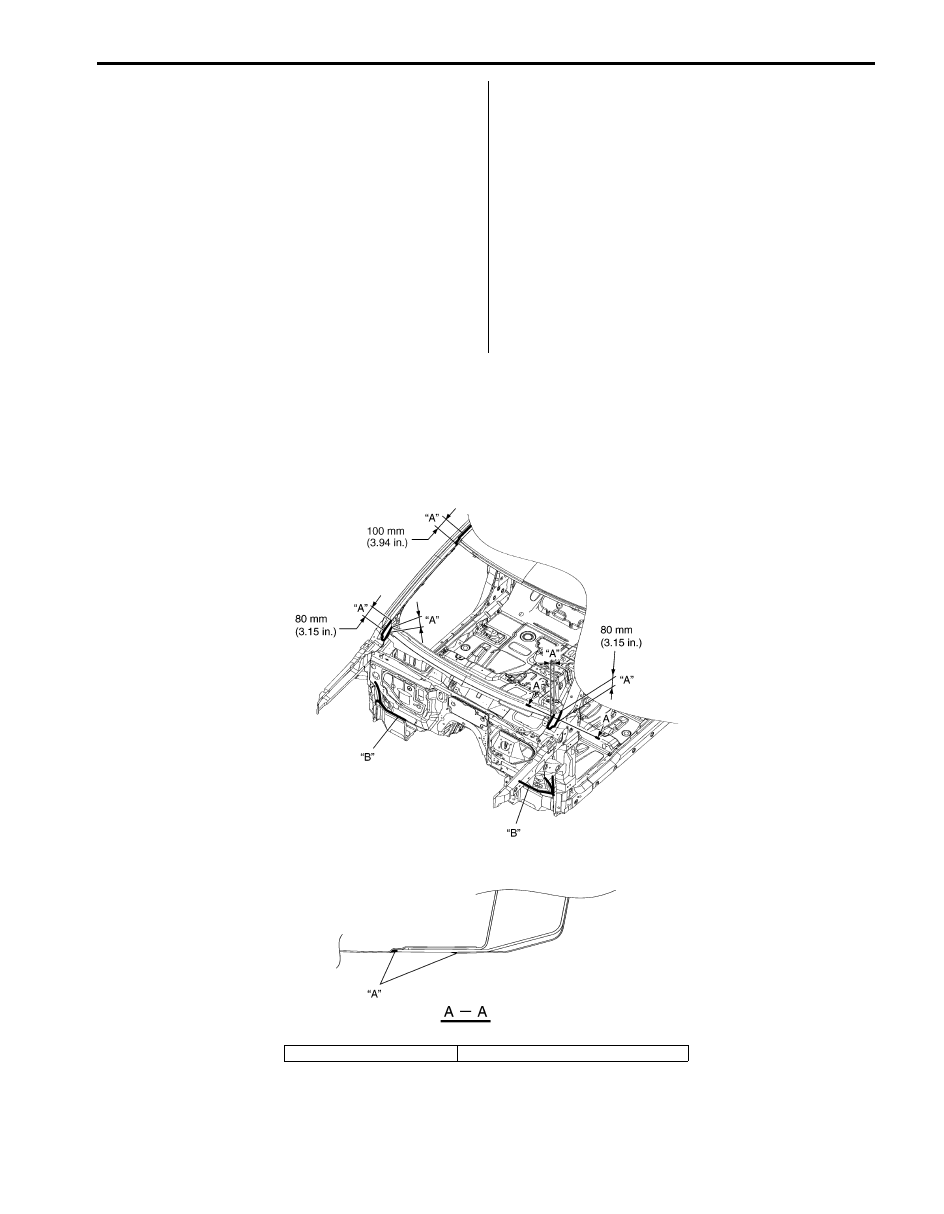
Sealant Application Areas
S6JB0B9C03001
Front Structure Panel
I5JB0A9C0001-03
“A”: Flatten sealant.
“B”: Smooth out sealant with a brush.
Нет комментариевНе стесняйтесь поделиться с нами вашим ценным мнением.
Текст