Suzuki Grand Vitara JB627. Service manual — part 227
5A-92 Automatic Transmission/Transaxle:
Installation
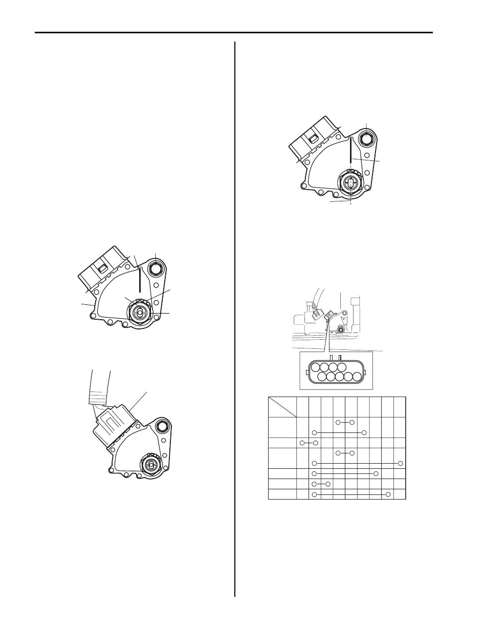
1) Install transmission range sensor (3) and tighten
sensor bolt (4) temporarily.
2) Install grommet, lock washer (1) and manual shift
shaft nut (2).
Tighten nut to specified torque. After tightening it,
bend claws of lock washer (1).
Tightening torque
Manual shift shaft nut (a): 7 N·m (0.7 kgf-m, 5.0
lb-ft)
3) After turning manual shift shaft fully
counterclockwise, turn it clockwise by 2 notches and
set it to “N” range.
4) With “N” reference line (5) on range sensor and shaft
center (6) aligned, tighten transmission range sensor
bolt (4) to specified torque.
Tightening torque
Transmission range sensor bolt (b): 13 N·m (1.3
kgf-m, 9.5 lb-ft)
5) Connect transmission range sensor connector (1).
6) Connect negative cable at battery.
Transmission Range Sensor Inspection and
Adjustment
S6JB0B5106014
1) Manual select lever to “N” range.
2) Check that center line (2) on manual shift and “N”
reference line (1) on sensor are aligned. If not,
loosen sensor bolt (3) and align them.
3) Check that engine starts in “N” and “P” ranges but it
doesn’t start in “D”, “4”, “3”, “L” or “R” range. Also,
check that back-up light lights in “R” range.
If faulty condition cannot be corrected by adjustment,
disconnect transmission range sensor connector
and check that continuity exists as shown by moving
select lever.
6
5
4, (b)
3
1
2, (a)
I4JA01512012-01
1
I6JB01510021-01
3
1
2
I6JB01510022-01
P
R
N
D
3
L
1
2
3
4
5
6
7
8
9
[B]
[A]
1
2
3
4
5
6
7
8
9
I6JB01510023-01
Automatic Transmission/Transaxle: 5A-93
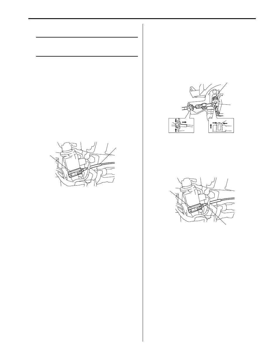
Key Interlock Cable Removal and Installation
S6JB0B5106015
NOTE
Do not bend interlock cable excessively
when removing and installing it, or system
will not operate correctly.
Removal
1) Disconnect negative (–) cable from battery.
2) If equipped with air bag system, disable air bag
system. Refer to “Disabling Air Bag System in
Section 8B”.
3) Remove steering column hole cover.
4) Tilt steering column if steering column is adjustable.
If no adjustable, loosen steering column bolts.
5) Remove steering column cover.
6) Turn ignition switch to ACC position.
7) Pull out key interlock cable (1) from key cylinder
cover (2) while pressing checkhook with slotted
screwdriver or the like.
8) Turn ignition switch to LOCK position.
9) Remove front console box.
10) Detach cable end (1) from interlock cam (2) while
pressing claws (3) of interlock cam boss.
At this time, be careful not to cause damage to its
claws.
Detach cable casing cap (4) from selector bracket
(5) while pressing checkhook.
11) Remove interlock cable.
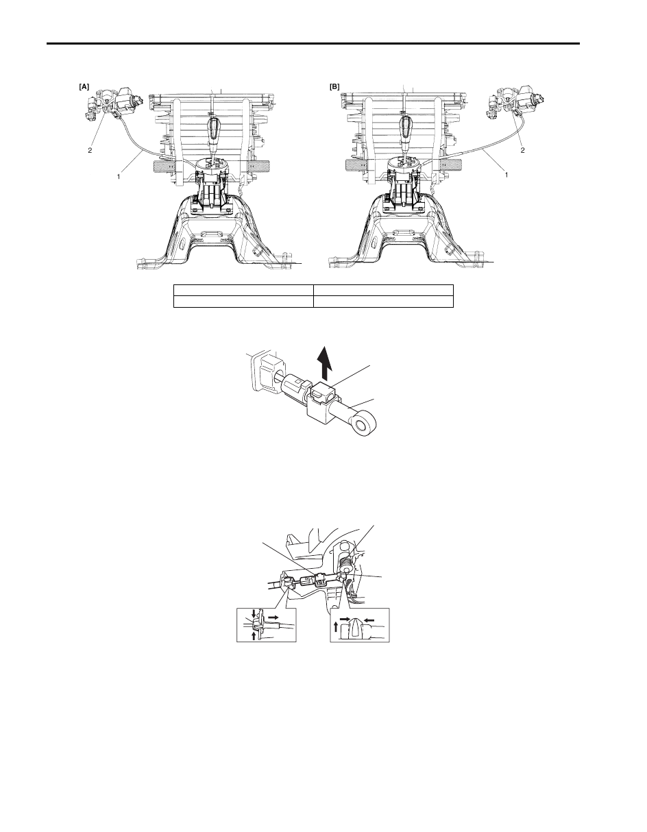
Installation
1) Lay interlock cable to its original cabling route.
2) Turn ignition switch to “ACC” position.
3) Insert cable casing cap (1) into key cylinder cover (2)
securely.
2
1
I5JB0A510062-01
4
5
3
2
1
I5JB0A510063-01
2
1
I5JB0A510064-01
5A-94 Automatic Transmission/Transaxle:
4) Pass and connect interlock cable as shown in the figure.
5) Pull out lock button (1) of selector side cable end (2).
6) Shift selector lever to “N” position.
7) Install cable casing cap (3) or selector bracket (4).
8) Connect cable end (1) to interlock cam (2) with ignition switch turned to “ACC” position.
9) Drive lock button (5) in cable end until it locks cable expansion and contraction.
10) Install steering column cover.
11) If the vehicle is equipped with air bag system, connect negative cable at battery and enable air bag system,
referring to “Enabling Air Bag System in Section 8B”.
I6JB0B510007-03
[A]: LHD model
1. Interlock cable
[B]: RHD model
2. Key cylinder
1
2
I5JB0A510066-01
4
5
3
2
1
I5JB0A510067-01
Automatic Transmission/Transaxle: 5A-95
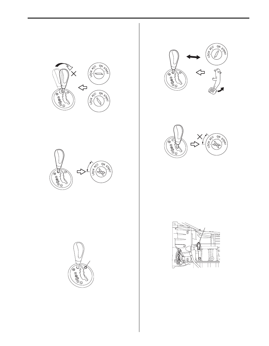
Brake and key Interlock System Inspection
S6JB0B5106016
1) Check that selector lever cannot be moved to any
other range from “P” range position when ignition
switch key is at ACC position, at LOCK position or it
is removed from keyhole of ignition switch, or brake
pedal is not depressed.
2) Shift select lever to “P” range position, release knob
button and check for the following.
• Ignition key can be turned between LOCK and
ACC positions back and forth and also it can be
removed from ignition switch.
• With shift lock solenoid release button (1) pushed
and ignition key turned to ACC position, selector
lever can be shifted from “P” range position to any
other range.
• With shift lock solenoid release button (1) pushed
and ignition key turned to LOCK position, selector
lever can not be shifted from “P” range position to
any other range.
• When ignition switch is turned ON and brake
pedal is depressed, selector lever can be shifted
from “P” range position to any other range.
3) With ignition lever shifted to any position other than
“P” range, check that ignition key cannot be turned
LOCK position and it cannot be removed from
ignition switch unless it is at LOCK position.
Input Shaft Speed Sensor Removal and
Installation
S6JB0B5106017
Removal
1) Disconnect negative cable at battery.
2) Hoist vehicle.
3) Disconnect input shaft speed sensor connector.
4) Remove input shaft speed sensor (1) from
transmission.
I5JB0A510165-01
I5JB0A510166-01
1
I5JB0A510167-01
I5JB0A510169-01
I5JB0A510170-01
1
I4JA01512018-01
Нет комментариевНе стесняйтесь поделиться с нами вашим ценным мнением.
Текст