Suzuki Grand Vitara JB627. Service manual — part 95
1D-61 Engine Mechanical:
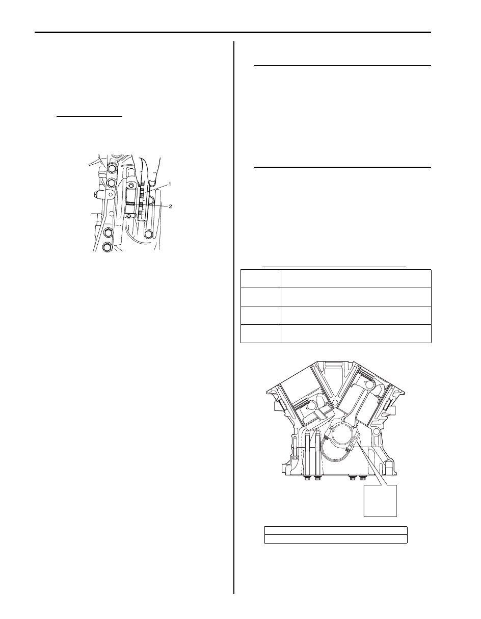
e. Remove cap and using a scale (2) on gaging
plastic (1) envelope, measure gaging plastic (1)
width at the widest point (clearance).
If clearance exceed its limit, use a new standard
size bearing referring to “Selection of Connecting
Rod Bearings” in this section.
After selecting new bearing, recheck clearance.
Bearing clearance
Standard: 0.045 – 0.063 mm (0.0018 – 0.0024
in.)
Limit: 0.08 mm (0.0031 in.)
f.
If clearance can not be brought to within its limit
even by using a new standard size bearing,
regrind crankpin to undersize and use 0.25 mm
undersize bearing as follows.
i.
Install 0.25 mm undersize bearing to
connecting rod big end.
ii. Measure bore diameter of connecting rod big
end.
iii. Regrind crank pin to the following finished
diameter.
iv. Confirm that bearing clearance is within
standard value described at step e).
• Selection of connecting rod bearings:
NOTE
• If bearing is in malcondition, or bearing
clearance is out of specification, select a
new standard bearing according to the
following procedure and install it.
• When replacing crankshaft or connecting
rod and its bearing due to any reason,
select new standard bearings to be
installed by referring to numbers stamped
on connecting rod and its cap and/or
alphabets stamped on crank web No.3.
a. Check stamped numbers on connecting rod and
its cap as shown.
Three kinds of numbers (“1”, “2” and “3”)
represent the following connecting rod big end
inside diameters.
For example, stamped number “1” indicates that
corresponding connecting rod big end inside
diameter is 53.0000 – 53.0060 mm (2.0867 –
2.0868 in.).
Connecting rod big end inside diameter
Finished crank
pin diameter
=
Measured big end
bore diameter
(including undersize
bearing)
–
0.054 mm
(0.0021 in.)
I6JB01140099-01
Stamped
numbers
connecting rod big end inside diameter
1
53.0000 – 53.0060 mm
(2.0867 – 2.0868 in.)
2
53.0061 – 53.0120 mm
(2.0869 – 2.0870 in.)
3
53.0121 – 53.0180 mm
(2.0871 – 2.0873 in.)
[A]: Weight indication mark
[B]: Connecting rod big end inside diameter number
[A]
D
[B]
2
I6JB01140100-01
Engine Mechanical: 1D-62
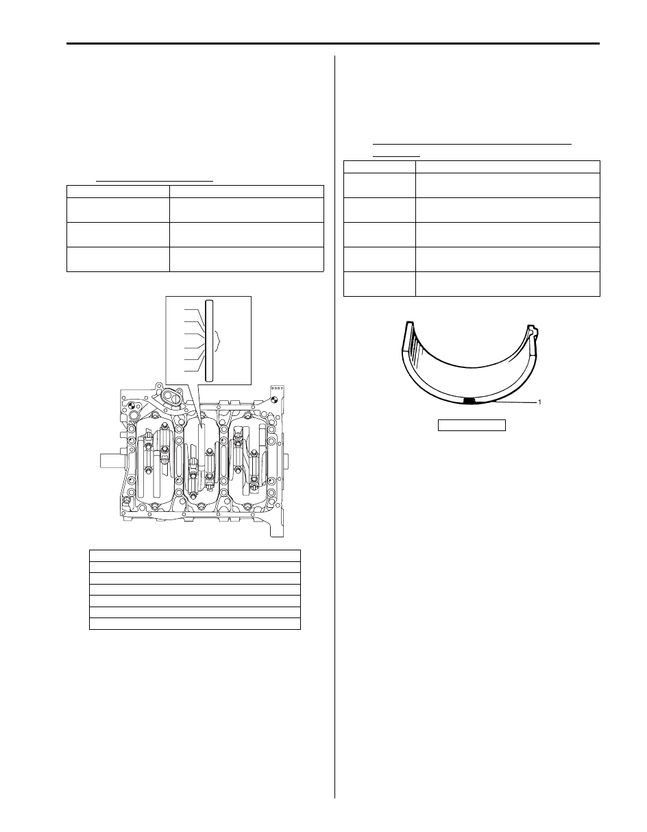
b. Next, check crankshaft pin diameter. On crank
web No.3, six alphabets are stamped as shown in
figure.
Three kinds of alphabet (“A”, “B” and “C”)
represent the following crankshaft pin diameter
respectively.
For example, stamped “A” indicates that
corresponding crankshaft pin diameter is 49.9940
– 50.0000 mm (1.9683 – 1.9685 in.).
Crankshaft pin diameter
c. There are five kinds of standard bearings differing
in thickness. To distinguish them, they are painted
in the following colors at the position as indicated
in figure.
Each color indicated the following thickness at the
center of bearing.
Standard size of connecting rod bearing
thickness
Stamped alphabet
Crankshaft pin diameter
A
49.9940 – 50.0000 mm
(1.9683 – 1.9685 in.)
B
49.9880 – 49.9939 mm
(1.9681 – 1.9682 in.)
C
49.9820 – 49.9879 mm
(1.9678 – 1.9680 in.)
[A]: Crankshaft pin diameter for No.1 cylinder
[B]: Crankshaft pin diameter for No.2 cylinder
[C]: Crankshaft pin diameter for No.3 cylinder
[D]: Crankshaft pin diameter for No.4 cylinder
[E]: Crankshaft pin diameter for No.5 cylinder
[F]: Crankshaft pin diameter for No.6 cylinder
[G]: Crankshaft journal outside diameter tolerance mark
A
B 4
5
6
7
B
C
A
A
[A]
[B]
[C]
[D]
[E]
[F]
[G]
I6JB01140101-01
Color painted
Bearing thickness
Blue
1.494 – 1.497 mm
(0.05882 – 0.05893 in.)
Yellow
1.491 – 1.494 mm
(0.05871 – 0.05881 in.)
Nothing
1.488 – 1.491 mm
(0.05859 – 0.05870 in.)
Black
1.485 – 1.488 mm
(0.05847 – 0.05858 in.)
Green
1.482 – 1.485 mm
(0.05835 – 0.05846 in.)
1. Paint
IYSQ01141169-01
1D-63 Engine Mechanical:
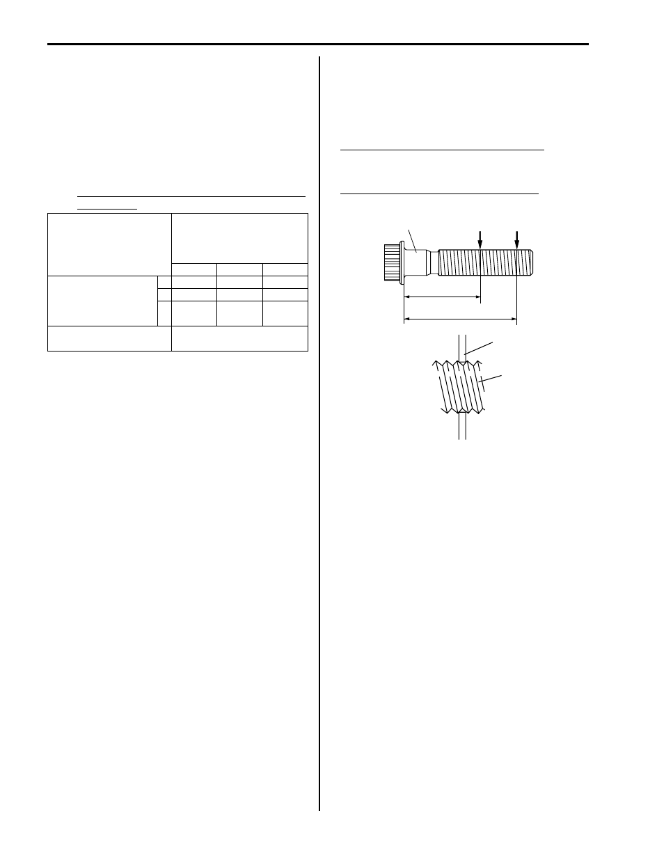
d. From number stamped on connecting rod and its
cap and alphabets stamped on crank web No.3,
determine new standard bearing to be installed to
connecting rod big end inside, by referring to
table.
For example, if number stamped on connecting
rod and its cap is “1” and alphabet stamped on
crank web No.3 is “B”, install a new standard
bearing painted in “Black” to its connecting rod big
end inside.
Specification of new standard connecting rod
bearing size
e. Check bearing clearance with newly selected
standard bearing referring to “Selection of
Connecting Rod Bearing” in this section.
If clearance still exceeds its limit, use next thicker
bearing and recheck clearance.
• Selection of connecting rod bearings:
Measured each thread diameter of connecting rod
bolts (1) at specified measurement points “A” and “B”
by using a micrometer (2).
Calculate difference in diameters (“A” – “B”). If it
exceeds limit, replace connecting rod.
Connecting rod bolt measurement points
“a”: 28.5 mm (1.12 in.)
“b”: 42.0 mm (1.65 in.)
Connecting rod bolt diameter difference
Limit: (“A” – “B”): 0.1 mm (0.004 in.)
Number stamped on
connecting rod and its cap
(connecting rod big end
inside diameter)
1
2
3
Alphabet stamped on
crank web No.3
(Crankshaft pin outer
diameter)
A Green
Black
Nothing
B
Black
Nothing Yellow
C Nothing Yellow
Blue
New standard bearing to
be installed.
1
2
1
‘‘a’’
‘‘b’’
‘‘A’’
‘‘B’’
I4RH01140043-01
Engine Mechanical: 1D-64
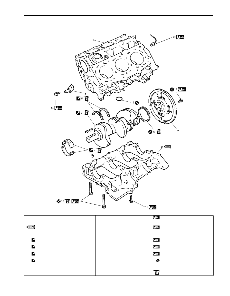
Main Bearings, Crankshaft and Cylinder Block Components
S6JB0B1406043
I6JB0B140001-01
1. Cylinder block
8. Timing chain oil jet
: Tighten 30 N
⋅m (3.0 kgf-m, 22.0 lb-ft), 42
N
⋅m (4.2 kgf-m, 30.5 lb-ft) and 40° by the
specified procedure.
2. Lower crankcase:
Apply sealant 99000-31260 referring to
“Installation” under “Main Bearings, Crankshaft
and Cylinder Block Removal and Installation”.
9. O-ring
: Tighten 27 N
⋅m (2.7 kgf-m, 19.5 lb-ft) by the
specified procedure.
3. Crankshaft:
Apply engine oil to crankshaft journals.
10. Crankcase bolt (10 mm (0.39 in.) thread
diameter)
: 70 N
⋅m (7.0 kgf-m, 51.0 lb-ft)
4. Main bearing:
Apply engine oil to bearing inside surfaces only.
11. Crankcase bolt (8 mm (0.31 in.) thread
diameter)
: 23 N
⋅m (2.3 kgf-m, 17.0 lb-ft)
5. Thrust bearing:
Set bearing facing grooved side to crank weds.
12. Knock sensor
: 11 N
⋅m (1.1 kgf-m, 8.0 lb-ft)
6. Rear oil seal:
Apply engine oil to contact part of crankshaft
with oil seal lip.
13. Flywheel (or drive plate) bolt
: Do not reuse.
7. Flywheel (M/T) / Drive plate (A/T)
14. Timing chain oil jet bolt
: Apply engine oil.
Нет комментариевНе стесняйтесь поделиться с нами вашим ценным мнением.
Текст