Suzuki Grand Vitara JB627. Service manual — part 224
5A-80 Automatic Transmission/Transaxle:
5
GRN/YEL
TCC pressure control
solenoid valve (+)
*0 – 0.6 V
↑↓
10 – 14 V
Engine running at idling.
(Output signal is duty pulse. Duty ratio varies
depending on torque converter clutch opening
condition.)
6
BLK/WHT Power source
10 – 14 V Ignition switch ON
7
WHT
CAN communication
line (active low signal)
*1.6 – 2.8 V
Engine running at specified idling speed.
(CAN communication signal is pulse. Pulse signal
frequency varies depending on engine condition.)
8
—
—
—
—
9
LT
GRN/RED
Pressure control
solenoid valve-B (–)
0.6 – 1.0 V Ignition switch ON
10
GRY
Transmission fluid
temperature sensor-B
(–) (if equipped)
0 – 1 V
Ignition switch ON
11
YEL/BLK
Transmission fluid
temperature sensor-A
(+)
2.9 – 3.1 V Ignition switch ON, fluid temperature is 20
°C (68 °F)
0.3 – 0.5 V Ignition switch ON, fluid temperature is 100
°C (212 °F)
12
ORN
Transmission fluid
temperature sensor-A
(–)
0 – 1 V
Ignition switch ON
13
—
—
—
—
14
GRN/RED Shift solenoid valve-E
0 – 1 V
Ignition switch ON
15
GRN/RED Shift solenoid valve-B
0 – 1 V
Ignition switch ON, select lever in “P” range
16
GRN
Shift solenoid valve-A
9 – 14 V
Ignition switch ON, select lever in “P” range
17
RED
CAN communication
line (active high signal)
*2.5 – 3.8 V
Engine running at specified idling speed.
(CAN communication signal is pulse. Pulse signal
frequency varies depending on engine condition.)
18
—
—
—
—
19
BRN/BLU
Pressure control
solenoid valve-C (–)
0.6 – 1.0 V Ignition switch ON
20
GRY/BLU
Transmission fluid
temperature sensor-B
(+) (if equipped)
2.9 – 3.1 V Ignition switch ON, fluid temperature is 20
°C (68 °F)
0.3 – 0.5 V Ignition switch ON, fluid temperature is 100
°C (212 °F)
21
LT GRN
Pressure control
solenoid valve-C (+)
*0 – 0.6 V
↑↓
10 – 14 V
Ignition switch ON, select lever in “P” range (Output
signal is duty pulse.)
22
LT
GRN/BLK
Pressure control
solenoid valve-B (+)
*0 – 0.6 V
↑↓
10 – 14 V
Engine running at idling
(Output signal is duty pulse.)
23
BLK/ORN Ground
0 – 1 V
Ignition switch ON
24
WHT
Power source for back-
up
10 – 14 V Constantly
Terminal
number
Wire color
Circuit
Normal
Voltage
Condition
Automatic Transmission/Transaxle: 5A-81
Connector “E93”
Terminal Wire color
Circuit
Standard
voltage
Condition
1
RED
Transmission range
sensor (“R” range)
8 – 14 V
Ignition switch ON, selector lever at “R” range
0 – 1 V
Ignition switch ON, selector lever at other than “R”
range
2
—
—
—
—
3
—
—
—
—
4
PNK/WHT 4L/N switch
8 – 14 V
Ignition switch ON, transfer position in 4H
0 – 1 V
Ignition switch OFF, transfer position in 4L and N
5
WHT
Output shaft speed
sensor (+)
2 – 3 V
Ignition switch turned ON, engine stops.
While engine running.
(Output signal is waveform. Waveform frequency
varies depending on output shaft speed. (18 pulses
are generated par 1 input shaft revolution.))
6
BLU
Input shaft speed
sensor (+)
2 – 3 V
Ignition switch turned ON, engine stops.
While engine running.
(Output signal is waveform. Waveform frequency
varies depending on input shaft speed. (24 pulses are
generated par 1 input shaft revolution.))
7
YEL/GRN
Transmission range
sensor (“D” range)
8 – 14 V
Ignition switch ON, selector lever at “R” range
0 – 1 V
Ignition switch ON, selector lever at other than “R”
range
8
PNK/BLU
Transmission range
sensor (“N” range)
8 – 14 V
Ignition switch ON, selector lever at “N” range
0 – 1 V
Ignition switch ON, selector lever at other than “N”
range
9
YEL/RED “4” position switch (+)
2.4 – 4.3 V Ignition switch ON, select lever in “P”, “N” or “D” range
8 – 14 V
Ignition switch ON, select lever in “R”, “3”, “2” or “L”
range
10
—
—
—
—
11
—
—
—
—
12
—
—
—
—
13
—
—
—
—
14
ORN
Output shaft speed
sensor (–)
2 – 3 V
Ignition switch ON, vehicle at stop
15
—
—
—
—
16
PNK
Input shaft speed
sensor (–)
2 – 3 V
Ignition switch ON, engine at stop
17
—
—
—
—
18
GRN/WHT
Transmission range
sensor (“L” range)
8 – 14 V
Ignition switch ON, select lever at “L” range
0 – 1 V
Ignition switch ON, select lever at other than “L” range
19
GRN/ORN
Transmission range
sensor (“3” range)
8 – 14 V
Ignition switch ON, select lever at “3” range
0 – 1 V
Ignition switch ON, select lever at other than “3” range
20
PNK/GRN
Transmission range
sensor (“P” range)
8 – 14 V
Ignition switch ON, select lever at “P” range
0 – 1 V
Ignition switch ON, select lever at other than “P” range
21
YEL/BLK
“4” position switch (–)
0 – 1 V
Ignition switch ON
22
—
—
—
—
23
PPL/WHT Data link connector
8 – 14 V
Ignition switch ON
24
—
—
—
—
25
—
—
—
—
26
—
—
—
—
5A-82 Automatic Transmission/Transaxle:
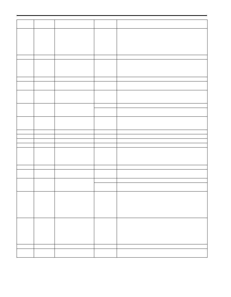
Reference Waveform No. 1
Pressure control solenoid valve-A signal at ignition
switch ON position
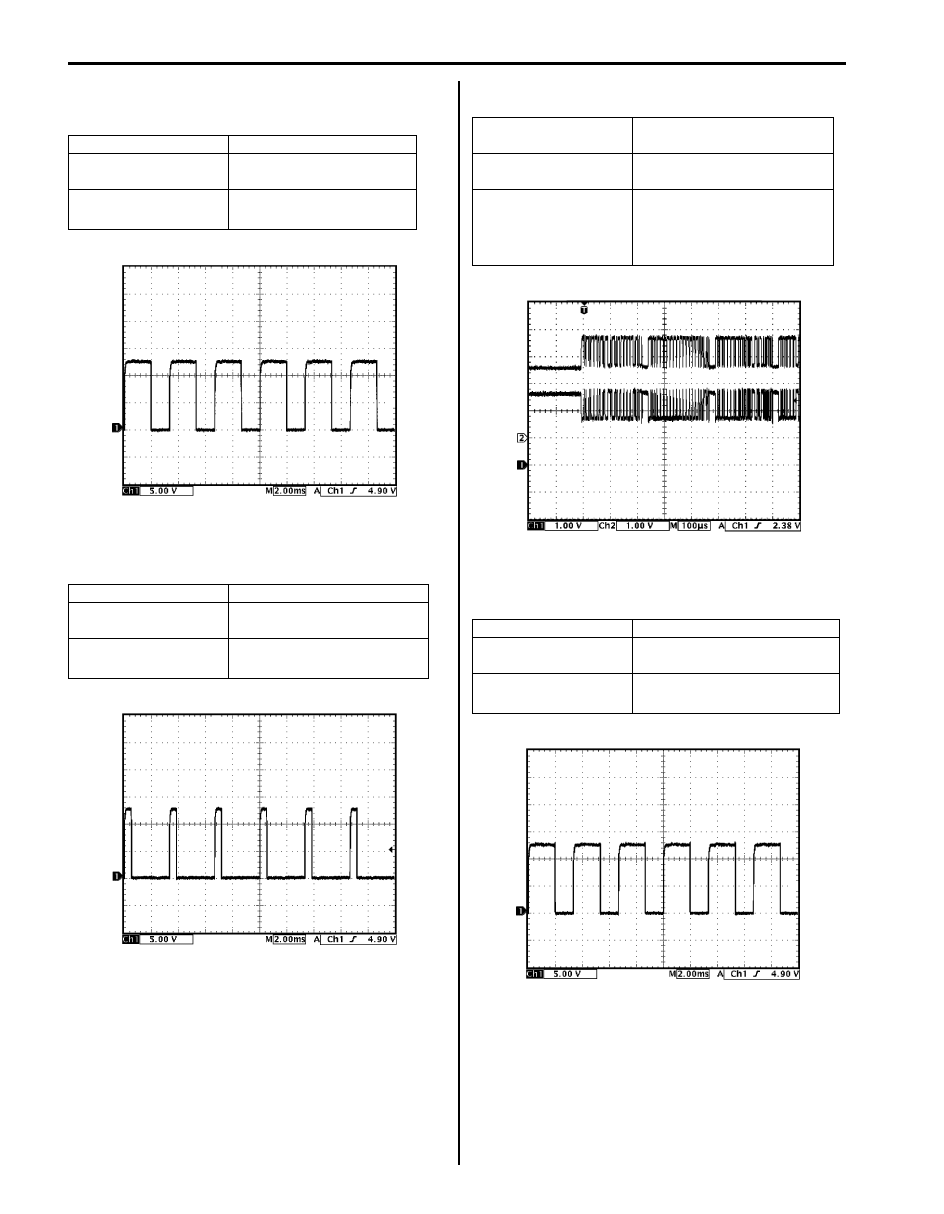
Reference Waveform No. 2
TCC pressure control solenoid valve signal at ignition
switch ON position
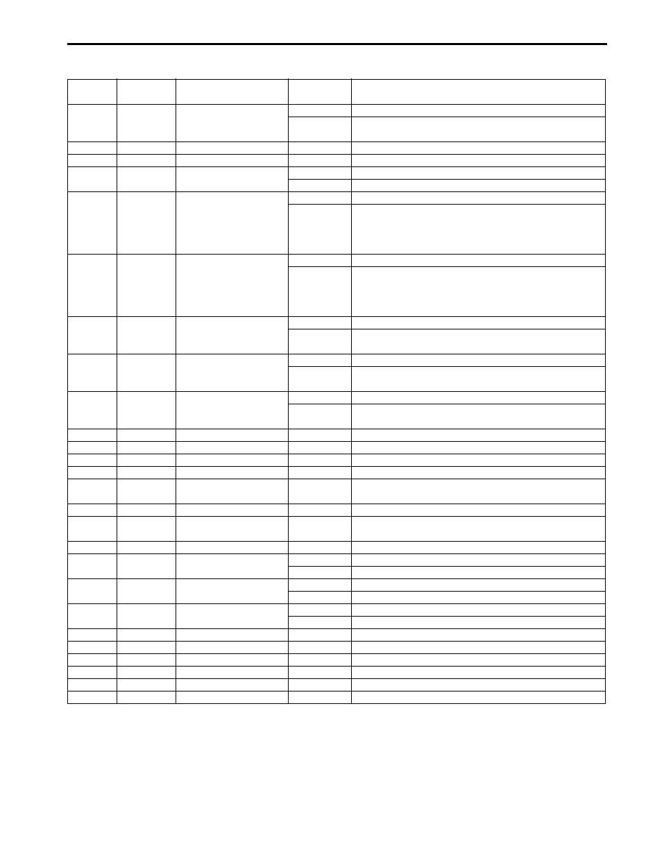
Reference Waveform No. 3
CAN communication line signal at engine idling
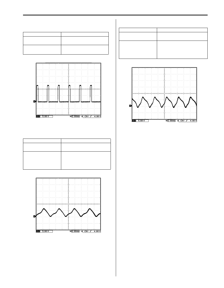
Reference Waveform No. 4
Pressure control solenoid valve-C signal at ignition
switch ON position
Measurement terminal CH1: E92-4 to E92-1
Oscilloscope setting
CH1: 5 V/DIV
TIME: 2 ms/DIV
Measurement condition
• Ignition switch turned ON
• Select lever at “P” range
Measurement terminal CH1: E92-5 to E92-1
Oscilloscope setting
CH1: 5 V/DIV
TIME: 2 ms/DIV
Measurement condition
• Ignition switch turned ON
• Select lever at “P” range
I4JA01512340-01
I4JA01512344-01
Measurement terminal
CH1: E92-17 to E92-1, CH2:
E92-7 to E92-1
Oscilloscope setting
CH1: 1 V/DIV, CH2: 1 V/DIV
TIME: 100
µs/DIV
Measurement condition
• After warmed up to normal
operating temperature
• Engine at idling speed
(700 r/min.)
Measurement terminal CH1: E92-21 to E92-1
Oscilloscope setting
CH1: 5 V/DIV
TIME: 2 ms/DIV
Measurement condition
• Ignition switch turned ON
• Select lever at “P” range
I4JA01512345-01
I4JA01512339-01
Automatic Transmission/Transaxle: 5A-83
Reference Waveform No. 5
Pressure control solenoid valve-B signal at ignition
switch ON position
Reference Waveform No. 6
Output shaft speed sensor signal at vehicle speed 20
km/h, 12.5 mile/h
Reference Waveform No. 7
Input shaft speed sensor signal at engine idling
Measurement terminal CH1: E92-22 to E92-1
Oscilloscope setting
CH1: 5 V/DIV
TIME: 2 ms/DIV
Measurement condition
• Ignition switch turned ON
• Select lever at “P” range
Measurement terminal CH1: E93-5 to E92-1
Oscilloscope setting
CH1: 5 V/DIV
TIME: 2 ms/DIV
Measurement condition
• After warmed up to normal
operating temperature
• Vehicle speed at 20 km/h,
12.5 mile/h
I4JA01512343-01
I4JA01512342-01
Measurement terminal CH1: E93-6 to E92-1
Oscilloscope setting
CH1: 5 V/DIV
TIME: 2 ms/DIV
Measurement condition
• After warmed up to normal
operating temperature
• Engine at idling speed (700
r/min.)
I4JA01512341-01
Нет комментариевНе стесняйтесь поделиться с нами вашим ценным мнением.
Текст