Suzuki Grand Vitara JB627. Service manual — part 111
1H-6 Ignition System:
Repair Instructions
Ignition Timing Inspection
S6JB0B1806001
NOTE
Before starting engine, place transmission
gear shift lever in “Neutral” (shift selector
lever to “P” range for A/T model), and set
parking brake.
1) Start engine and warm it up to normal operating
temperature.
2) Make sure that all of electrical loads except ignition
are switched OFF.
3) Check to be sure that idle speed is within
specification referring to “Idle Speed and IAC
Throttle Valve Opening Inspection in Section 1A”.
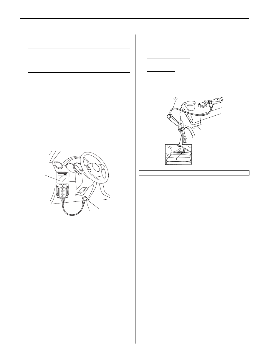
4) Connect SUZUKI scan tool to DLC (1) with ignition
switch OFF, restart engine and fix ignition timing by
using fixed spark mode of SUZUKI scan tool.
Special tool
(A): SUZUKI scan tool
5) Set timing light to ignition harness for No.1 cylinder.
6) Using timing light, check that timing observed from
viewpoint is within specification.
Initial ignition timing
Fixed with SUZUKI scan tool: 5
± 1° BTDC
Ignition order
1-6-5-4-3-2
Special tool
(A): 09930–76420
7) If ignition timing is out of specification, check the
followings.
• CKP sensor
• CKP sensor plate
• TP sensor
• CMP sensor
• CMP sensor rotor tooth of camshaft
• Wheel speed sensor (VSS)
• Timing chain cover installation
8) After checking initial ignition timing, release ignition
timing fixation by using scan tool.
9) With engine idling (throttle opening at closed position
and vehicle stopped), check that ignition timing is
about 10
°– 16° BTDC. (Constant variation within a
few degrees from 10
° – 156° BTDC indicates no
abnormality but proves operation of electronic timing
control system.) Also, check that increasing engine
speed advances ignition timing.
If the check results are not satisfactory, check CKP
sensor and ECM.
(A)
1
I5JB0A510016-01
1. Timing mark on crankshaft pulley
I6JB01180004-02
Ignition System: 1H-7
Ignition Coil Assembly (Igniter and Ignition
Coil) Removal and Installation
S6JB0B1806002
Removal
1) Remove surge tank cover.
2) Disconnect ignition coil coupler.
3) Remove ignition coil bolt (1), and then pull out
ignition coil assembly (2).
Installation
Install in reverse order of removal.
Tightening torque
Ignition coil bolt (a): 6.5 N·m (0.65 kgf-m, 5.0 lb-ft)
Ignition Coil Assembly (Igniter and Ignition
Coil) Inspection
S6JB0B1806003
Check ignition coil assembly for the following:
• Damage
• Deterioration
• Terminal for corrosion
Spark Plug Removal and Installation
S6JB0B1806004
Removal
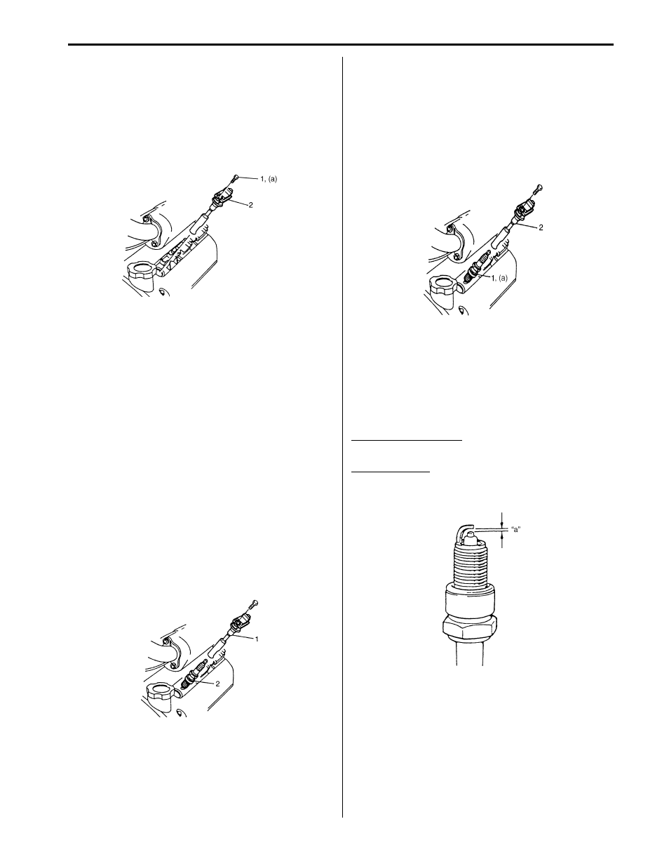
1) Remove ignition coil assembly (1) referring to
“Ignition Coil Assembly (Igniter and Ignition Coil)
Removal and Installation”.
2) Remove spark plug (2).
Installation
1) Install spark plug (1) and tighten them to specified
torque.
Tightening torque
Spark plug (a): 25 N·m (2.5 kgf-m, 18.0 lb-ft)
2) Install ignition coil assembly (2) referring to “Ignition
Coil Assembly (Igniter and Ignition Coil) Removal
and Installation”.
Spark Plug Inspection
S6JB0B1806005
Inspect them for electrode, air gap wear carbon deposits
and Insulator damage.
If any abnormality is found, adjust air gap, clean with
spark plug cleaner or replace them with specified new
plug.
Spark plug air gap “a”
: 1.0 – 1.1 mm (0.039 – 0.043 in.)
Spark plug type
DENSO: K20PR-U11
NGK: BKR6E-11
I6JB01180005-02
I4JA01180002-01
I4JA01180003-01
IYSQ01181012-01
1H-8 Ignition System:
Specifications
Tightening Torque Specifications
S6JB0B1807001
Reference:
For the tightening torque of fastener not specified in this section, refer to “Fastener Information in Section 0A”.
Special Tools and Equipment
Special Tool
S6JB0B1808001
Fastening part
Tightening torque
Note
N
⋅m
kgf-m
lb-ft
Ignition coil bolt
6.5
0.65
5.0
Spark plug
25
2.5
18.0
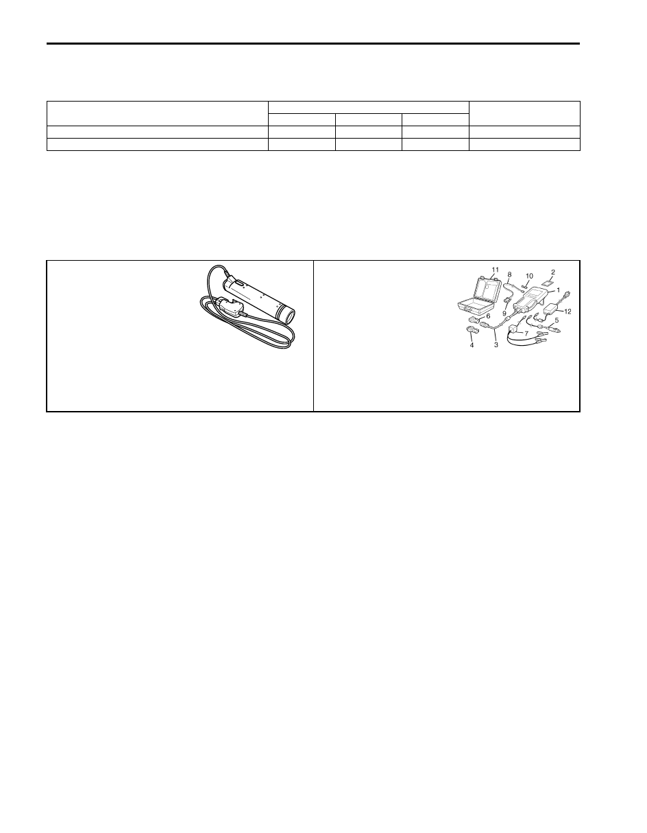
09930–76420
SUZUKI scan tool
Timing-light (dry cell type)
—
This kit includes following
items. 1. Tech 2, 2. PCMCIA
card, 3. DLC cable, 4. SAE
16/19 adapter, 5. Cigarette
cable, 6. DLC loop back
adapter, 7. Battery power
cable, 8. RS232 cable, 9.
RS232 adapter, 10. RS232
loop back connector, 11.
Storage case, 12. )
Starting System: 1I-1
Engine
Starting System
General Description
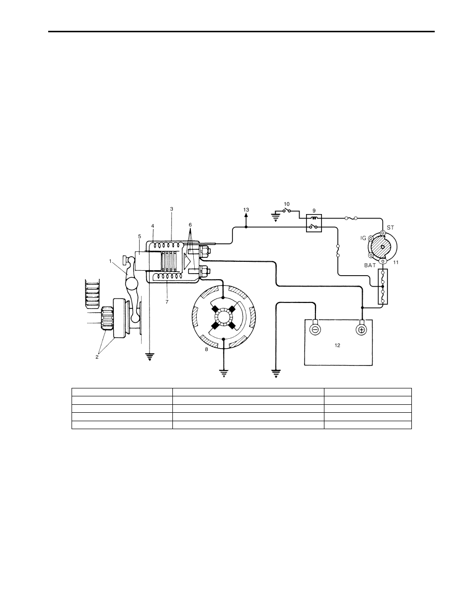
Cranking Circuit Introduction
S6JB0B1901001
The cranking circuit consists of the battery, starting motor, ignition switch, and related electrical wiring. These
components are connected electrically.
Starting Motor Circuit Description
S6JB0B1901002
• The magnetic switch coils are magnetized when the ignition switch is closed.
• The resulting plunger and pinion drive lever movement causes the pinion to engage the engine flywheel gear and
the magnetic switch main contacts to close, and cranking takes place.
• When the engine starts, the pinion over-running clutch protects the armature from excessive speed until the switch
is opened, at which time the return spring causes the pinion to disengage.
I5JB0A190004-01
1. Pinion drive lever
6. Magnetic switch contacts
11. Ignition & Starter switch
2. Pinion & Over-running clutch
7. Pull-in coil
12. Battery
3. Magnetic switch
8. Starting motor
13. To ECM
4. Hold-in coil
9. Starting motor control relay
5. Plunger
10. A/T: Transmission range switch (shift lever switch)
Нет комментариевНе стесняйтесь поделиться с нами вашим ценным мнением.
Текст