Suzuki Grand Vitara JB627. Service manual — part 251
5B-27 Manual Transmission/Transaxle:
12) Tighten countershaft front bearing nut to specified
torque while locking counter shaft in the same
manner as step 2) of “Disassembly” under
“Countershaft Disassembly and Assembly”.
CAUTION
!
Do not hold spline, gear teeth or abrasived
surface of shaft with vise through “V” blocks
or the like, otherwise shaft may be damaged.
Tightening torque
Countershaft front bearing nut: 210 N·m (21.0
kgf-m, 152.0 lb-ft)
13) Caulk countershaft front bearing nut using caulking
tool and hammer.
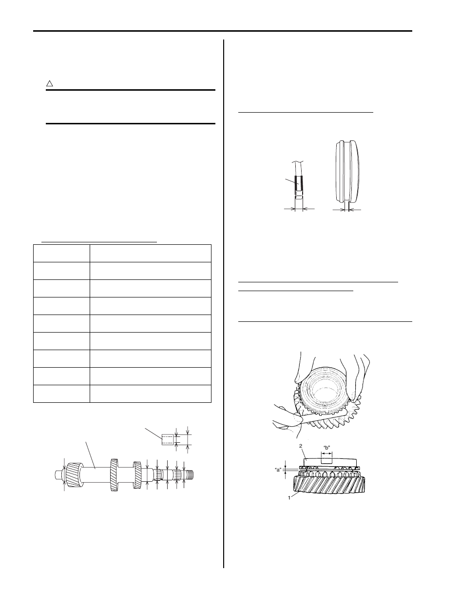
Countershaft and Reverse Idle Gear Inspection
S6JB0B5206026
• Using micrometer, check diameter of countershaft (1)
and needle bush (2) as shown. If measured value is
out of specification, replace counter and/or bush.
Countershaft diameter (standard)
• Measure width “a” of low speed gear shift fork and
groove width “b” of low speed gear synchronizer
sleeve and then calculate clearance “c” as follows:
If clearance exceeds limit, replace fork bush (1) and
sleeve.
Clearance “c” between fork and sleeve
Standard: 0.3 – 0.5 mm (0.012 – 0.020 in.)
Limit: 1.0 mm (0.039 in.)
• Check clearance “a” between synchronizer ring (2)
and gear (1), key slot width “b” in synchronizer ring
and each chamfered tooth of gear and synchronizer
ring and replace with new one, if necessary. Also,
check gear tooth.
Clearance “a” between synchronizer ring and
gear (Countershaft) (1st and 2nd)
Standard: 1.0 – 1.4 mm (0.040 – 0.055 in.)
Service limit: 0.5 mm (0.020 in.)
Key slot width “b” (1st and 2nd synchronizer ring)
Standard: 10.0 – 10.2 mm (0.394 – 0.401 in.)
Limit: 10.45 mm (0.411 in.)
Measuring
portion
Standard
“a”
25.002 – 25.015 mm
(0.9843 – 0.9848 in.)
“b”
27.987 – 28.000 mm
(1.1019 – 1.1023 in.)
“c”
27.987 – 28.000 mm
(1.1019 – 1.1023 in.)
“d”
30.959 – 30.975 mm
(1.2189 – 1.2194 in.)
“e”
34.975 – 34.991 mm
(1.3770 – 1.3775 in.)
“f”
30.002 – 30.015 mm
(1.1812 – 1.1816 in.)
“g”
28.000 – 28.013 mm
(1.1023 – 1.1028 in.)
“h”
34.975 – 34.991 mm
(1.3770 – 1.3776 in.)
“c”
“d”
“e”
“f”
“g”
“h”
“b”
“a”
1
2
I5JB0A520078-01
Clearance “c”
=
“b”
–
“a”
1
“a”
“b”
I5JB0A520055-01
I5JB0A520079-01
Manual Transmission/Transaxle: 5B-28
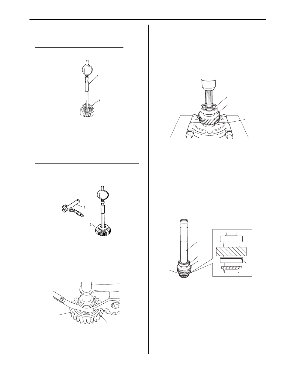
• Using cylinder gauge (1), check inside diameter of
countershaft 1st and 2nd gears (2). If measured value
exceeds specification, replace countershaft 5th gear.
Countershaft 1st and 2nd gears diameter
Standard: 40.000 – 40.025 mm (1.5748 – 1.5757 in.)
• Check oil clearance between reverse idle gear (2) and
shaft (1) measuring inside diameter “a” of gear and
diameter “b” of shaft and calculate as follows:
If clearance exceeds limit, replace gear and shaft.
Oil clearance “c” between reverse idle gear and
shaft
Standard: 0.016 – 0.045 mm (0.0006 – 0.0018 in.)
Limit: 0.13 mm (0.005 in.)
• Check clearance between reverse idle gear (2) and
lever (1) of reverse gear shift link.
If clearance exceeds limit, replace gear and lever.
Clearance between reverse idle gear and lever
Standard: 0.05 mm – 0.35 mm (0.002 – 0.014 in.)
Limit: 0.5 mm (0.020 in.)
Output Shaft Disassembly and Assembly
S6JB0B5206027
Disassembly
1) Remove output shaft rear snap ring.
2) Apply bearing puller to output shaft front bearing (1),
and drive out output shaft front bearing, output shaft
gear (2) and output shaft rear bearing (3) all at once
from output shaft using press.
Assembly
1) Clean all components thoroughly, inspect them for
any abnormality and replace with new ones as
necessary.
2) Put front bearing (1) onto output shaft facing groove
(4) side to output shaft gear (2) and drive in output
shaft front bearing, output shaft gear and output
shaft rear bearing (3) all together using special tool
and hammer.
Special tool
(A): 09940–51710
3) Install new output shaft rear snap ring.
Clearance “c”
=
“b”
–
“a”
IYSQ01522122-01
IYSQ01522123-01
1
2
I5JB0A520080-01
3
2
1
I5JB0A520081-01
(A)
3
2
1
4
I5JB0A520082-01
5B-29 Manual Transmission/Transaxle:
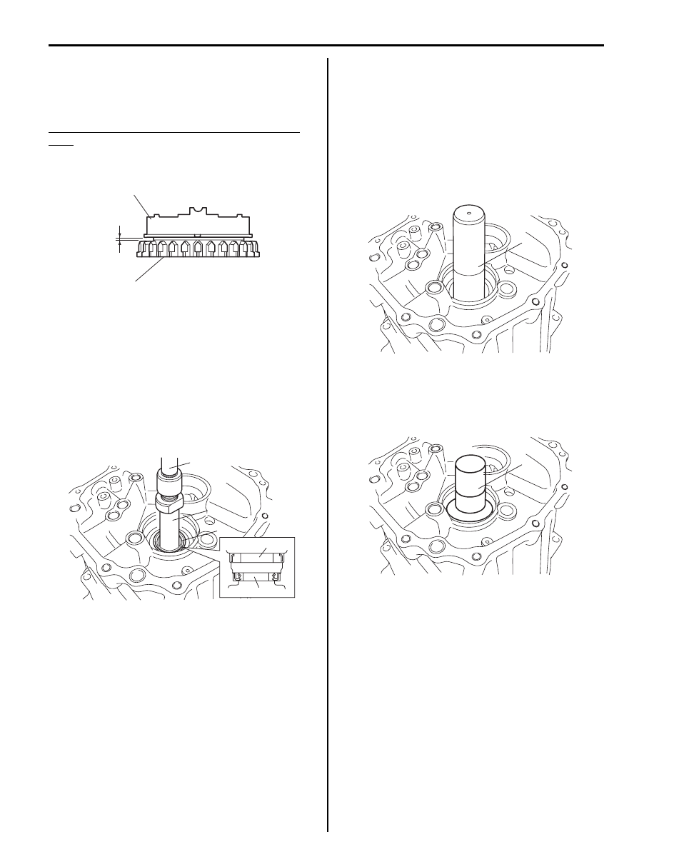
Output Shaft Inspection
S6JB0B5206028
Check clearance “a” between ring (2) and output shaft
(1), each chamfered teeth of gear, ring and sleeve, then
determine parts replacement.
Clearance between synchronizer ring and output
shaft
Standard “a”: 1.0 - 1.4 mm (0.040 - 0.055 in.)
Service limit “a”: 0.5 mm (0.020 in.)
Manual Transmission Front Case Disassembly
and Assembly
S6JB0B5206029
Disassembly
Remove pump seal (1) and oil seal (2) from front case
using special tools.
Special tool
(A): 09941–64511
(B): 09930–30104
Assembly
1) Set new oil seal to front case with its spring side
facing rear case side.
2) Install oil seal until it becomes flush with case
surface using special tool and hammer and apply
grease to oil seal lip.
Special tool
(A): 09940–51710
: Grease 99000–25010 (SUZUKI Super Grease A)
3) Install pump seal to front case using special tool and
hammer.
Special tool
(A): 09913–75810
“a”
1
2
I5JB0A520083-01
(B)
(A)
1
1
2
I5JB0A520084-02
(A)
I5JB0A520085-02
(A)
I5JB0A520088-01
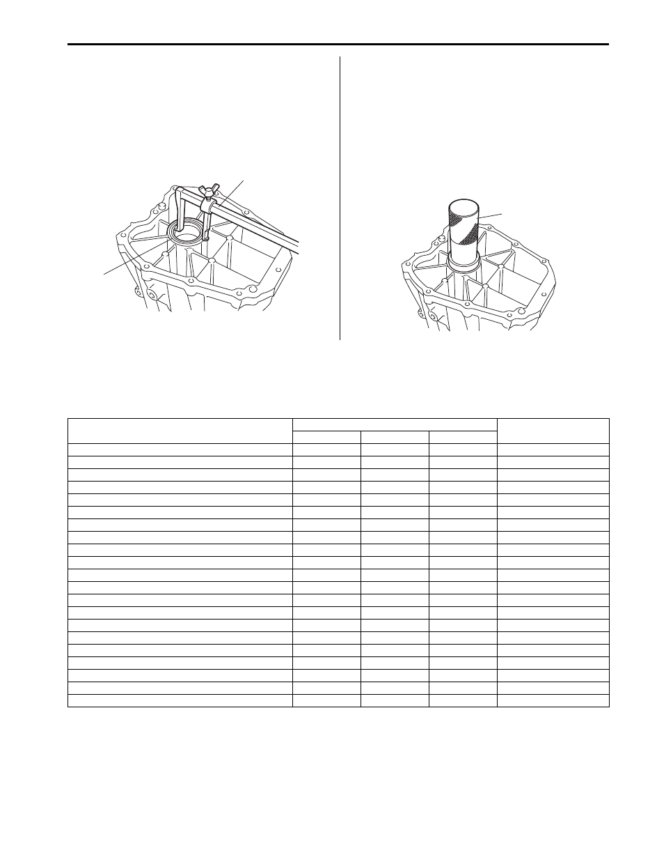
Manual Transmission/Transaxle: 5B-30
Manual Transmission Adapter Case
Disassembly and Assembly
S6JB0B5206030
Disassembly
Remove oil seal (1) from adapter case using special tool.
Special tool
(A): 09913–50121
Assembly
1) Set new oil seal to adapter case with its spring side
facing rear case side.
2) Install oil seal until it becomes flush with case
surface using special tool and hammer and apply
grease to oil seal lip.
Special tool
(A): 09913–85210
: Grease 99000–25010 (SUZUKI Super Grease A)
Specifications
Tightening Torque Specifications
S6JB0B5207001
(A)
1
I5JB0A520086-01
(A)
I5JB0A520087-01
Fastening part
Tightening torque
Note
N
⋅m
kgf-m
lb-ft
Transmission oil drain plug
23
2.3
17.0
Oil filler plug
23
2.3
17.0
Control lever locating bolt
9
0.9
6.5
Case cover bolt
10
1.0
7.5
Control lever boot cover bolt
12
1.2
9.0
Back up light switch
23
2.3
17.0
Plate bolt
23
2.3
17.0
Control shaft joint nut
18
1.8
13.0
Gear shift lever front case bolt
23
2.3
17.0
Engine rear mounting No.1 bolt
55
5.5
40.0
Engine rear mounting member bolt
55
5.5
40.0
Engine rear mounting No.2 bolt
55
5.5
40.0
Transmission to engine bolt and nut
85
8.5
61.5
Clutch housing lower plate bolt
11
1.1
8.0
Low gear shift inverse lever bolt
23
2.3
17.0
Transmission case bolt
23
2.3
17.0
Reverse shaft bolt
23
2.3
17.0
Gear shift locating bolt
23
2.3
17.0
Adapter case bolt
23
2.3
17.0
Input shaft 5th hub nut
210
21.0
152.0
Countershaft front bearing nut
210
21.0
152.0
Нет комментариевНе стесняйтесь поделиться с нами вашим ценным мнением.
Текст