Suzuki Grand Vitara JB627. Service manual — part 36
1A-93 Engine General Information and Diagnosis:
DTC P0137 / P0138: O2 Sensor Circuit Low Voltage / High Voltage (Sensor-2, Bank-1)
S6JB0B1104028
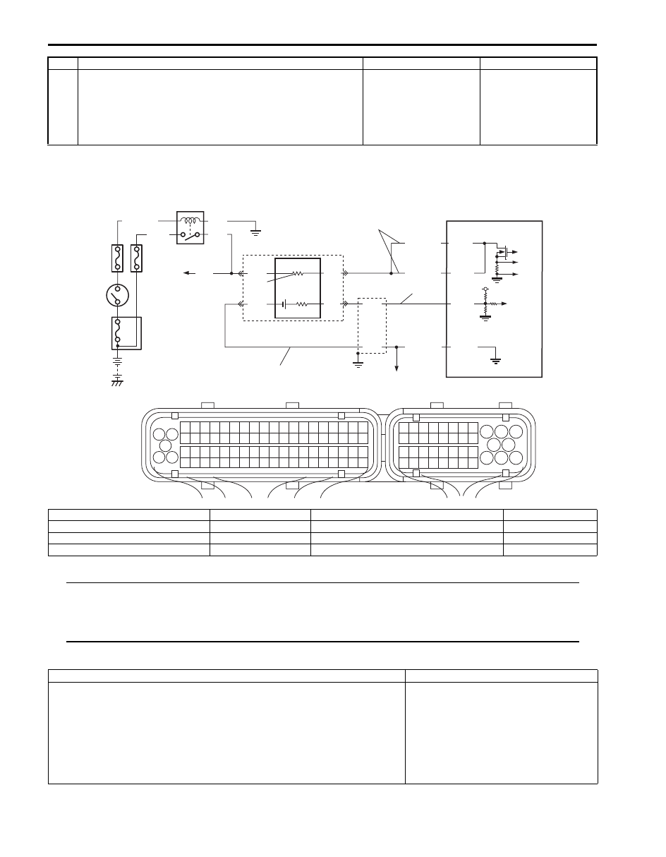
System and Wiring Diagram
NOTE
When DTC P0138 and P0158 are indicated together, it is possible that HO2S ground circuit (“GRN”)
wire is open.
When DTC P0138, P0158, P0107, P0113, P0118 and P0553 are indicated together, it is possible that
sensor ground circuit (“GRY/GRN”) wire is open.
DTC Detecting Condition and Trouble Area
4
A/F sensor heater check
1) Check heater resistance of A/F sensor (bank-1) referring
to “Air Fuel Ratio (A/F) Sensor On-Vehicle Inspection in
Section 1C”.
Is A/F sensor heater in good condition?
Substitute a known
good ECM and recheck.
If ECM OK, replace A/F
sensor (bank-1).
Replace A/F sensor
(bank-1).
Step
Action
Yes
No
4
3
9
RED
GRN
PNK
BLK
C37-2
C37-3
C37-67
6
2
7
10
BLK
BLU
WHT
BLK/RED
GRY/GRN
1
8
5
5V
BLK/WHT
BLK
PNK
GRN
C37-1
BLK/RED
1
3 2
4
5
6
7
8
9
1110
12
13
14
15
16
17
18
19
20
17
18
19
20
21
22
23
24
25
26
27
28
29
30
31
33
34
35
36
37
38
39
40
32
1
2
3
4
5
6
7
8
9
10
11
12
13
14
15
16
21
22
23
24
25
26
27
28
29
30
31
32
33
34
35
36
37
38
39
40
41
42
43
44
45
46
47
48
49
50
51
52
53
54
55
56
57
58
59
60
61
62
63
64
65
66
67
68
69
70
71
72
73
74
75
76
77
78
79
80
81
b
a
c
I6JB01110055-01
a. Signal circuit of HO2S (bank-1)
2. Shield wire
6. HO2S (bank-1)
10. To other sensors
b. Ground circuit of HO2S (bank-1)
3. Ignition Switch
7. HO2S heater
c. Control circuit of HO2S (bank-1) heater
4. O2 HTR fuse
8. To A/F sensor (bank-1 and -2), HO2S (bank-2)
1. HO2S heater relay
5. IG COIL fuse
9. ECM
DTC detecting condition
Trouble area
DTC P0137 O2 Sensor Circuit Low Voltage (Sensor-2, Bank-1):
Circuit voltage of HO2S (bank-1) is lower than 15 mV for more than 60 sec.
continuously with engine running except for fuel cut condition.
(2 driving cycle detection logic)
DTC P0138 O2 Sensor Circuit High Voltage (Sensor-2, Bank-1):
Circuit voltage of HO2S (bank-1) is higher than 1.2 V for more than 20 sec.
continuously with engine running.
(2 driving cycle detection logic)
• HO2S circuit
• HO2S
• ECM

Engine General Information and Diagnosis: 1A-94
DTC Confirmation Procedure
NOTE
Check to make sure that following conditions are satisfied when using this “DTC Confirmation
Procedure”.
• The following DTC is not detected: HO2S heater (when troubleshooting for DTC P0137).
1) With ignition switch OFF, connect scan tool to DLC.
2) Turn ON ignition switch and clear DTC.
3) Start engine and warm up to normal operating temperature.
4) Run engine at idle speed for 1 min. or more.
5) Check DTC and pending DTC.
DTC Troubleshooting
NOTE
Before this trouble shooting is performed, read the precautions for DTC troubleshooting referring to
“Precautions for DTC Troubleshooting”.
Step
Action
Yes
No
1
Was “Engine and Emission Control System Check”
performed?
Go to Step 2.
Go to “Engine and
Emission Control
System Check”.
2
HO2S signal check
1) Connect scan tool with ignition switch turned OFF
2) Warm up engine to normal operating temperature and
keep it at 2000 r/min. for 60 sec.
3) Repeat racing engine (Repeat depressing accelerator
pedal 5 to 6 times continuously to enrich A/F mixture and
take foot off from pedal to enlean it).
4) Check for HO2S (bank-1) output voltage displayed on
scan tool.
Does HO2S output voltage between 0.5 V and 0.8 V?
Intermittent trouble.
Check for intermittent
referring to “Intermittent
and Poor Connection
Inspection in Section
00”.
Go to Step 3.
3
HO2S circuit check
1) Disconnect connector from HO2S (bank-1) and ECM
with ignition switch turned OFF.
2) Check for proper terminal connection to HO2S (bank-1)
connector and ECM connector.
3) If connections are OK, check that HO2S (bank-1) circuit
is as follows.
• Wiring harness resistance of each “Signal circuit of
HO2S (bank-1)”, “Ground circuit of HO2S (bank-1)”
and “Control circuit of HO2S (bank-1) heater” is less
than 1
Ω.
• Insulation resistance between “Signal circuit of HO2S
(bank-1)” and vehicle body ground is infinity.
• Insulation resistance of wire harness is infinity
between “Signal circuit of HO2S (bank-1)” terminal
and each other terminal at HO2S (bank-1) connector.
• Circuit voltage between “Signal circuit of HO2S (bank-
1)” and vehicle body ground is 0 V with ignition switch
turned ON.
Are they in good condition?
Go to Step 4.
Repair or replace
defective wiring
harness.
1A-95 Engine General Information and Diagnosis:
DTC P0140: O2 Sensor Circuit No Activity Detected (Sensor-2, Bank-1)
S6JB0B1104029
Wiring Diagram
Refer to “DTC P0137 / P0138: O2 Sensor Circuit Low Voltage / High Voltage (Sensor-2, Bank-1)”
DTC Detecting Condition and Trouble Area
WARNING
!
• When performing a road test, select a place where there is no traffic or possibility of a traffic
accident and be very careful during testing to avoid occurrence of an accident.
• Road test should be carried out by 2 persons, a driver and a tester, on a level road.
NOTE
Check to make sure that following conditions are satisfied when using this “DTC Confirmation
Procedure”.
• Engine coolant temperature: 70
°C (158 °F) or more.
• Engine coolant temperature at engine start: –10
°C (14 °F) or more.
• Intake air temperature: –10
°C (14 °F) or more.
• Atmospheric pressure: higher than 75 kPa (560 mmHg) (Altitude: lower than 2790 m (9150 ft)).
• The following DTCs are not detected: MAF sensor, ECT sensor, IAT sensor, Fuel system, A/F sensor,
TP sensor, HO2S sensor heater and HO2S sensor (other than DTC P0140).
1) With ignition switch turned OFF, connect scan tool.
2) Turn ON ignition switch and clear DTC using scan tool.
3) Start engine and warm up to normal operating temperature.
4) Drive vehicle at 40 mph (60 km/h) or higher. (engine speed: 2500 – 3000 r/min.)
5) Keep above vehicle speed for 4 min. or more. (Throttle valve opening is kept constant in this step.)
6) Check if DTC and pending DTC exist by using scan tool. If not, check if oxygen sensor monitoring test has been
completed by using scan tool. If not in both of above checks (i.e., no DTC and pending DTC and oxygen sensor
monitoring test not completed), check vehicle condition (environmental) and repeat Step 3) through 6).
4
HO2S heater check
1) Check heater resistance of HO2S (bank-1) referring to
“Heated Oxygen Sensor (HO2S-2) Heater On-Vehicle
Inspection (If Equipped) in Section 1C”.
Is HO2S heater in good condition?
Substitute a known
good ECM and recheck.
If ECM OK, replace
HO2S (bank-1).
Replace HO2S (bank-
1).
Step
Action
Yes
No
DTC detecting condition
Trouble area
Circuit voltage of HO2S (bank-1) is within 0.27 V – 0.35 V for more than 120 sec.
continuously while A/F (fuel trim) is shifted rich to lean and lean to rich with specified
diagnosis frequency under specified running, or circuit voltage of HO2S (bank-1) is
out of specified range (0.2 V – 0.45 V) while engine is running with warmed it up from
cold start (ECT is less than 40
°C).
(2 driving cycle detection logic)
• HO2S sensor
• HO2S
• ECM

Engine General Information and Diagnosis: 1A-96
DTC Troubleshooting
NOTE
Before this trouble shooting is performed, read the precautions for DTC troubleshooting referring to
“Precautions for DTC Troubleshooting”.
Step
Action
Yes
No
1
Was “Engine and Emission Control System Check”
performed?
Go to Step 2.
Go to “Engine and
Emission Control
System Check”.
2
HO2S signal check
1) Connect scan tool with ignition switch turned OFF
2) Warm up engine to normal operating temperature and
keep it at 2000 r/min. for 60 sec.
3) Repeat racing engine (Repeat depressing accelerator
pedal 5 to 6 times continuously to enrich A/F mixture and
take foot off from pedal to enlean it).
4) Check for HO2S (bank-1) output voltage displayed on
scan tool.
Does HO2S output voltage between 0.5 V and 0.8 V?
Intermittent trouble.
Check for intermittent
referring to “Intermittent
and Poor Connection
Inspection in Section
00”.
Go to Step 3.
3
HO2S circuit check
1) Disconnect connector from HO2S (bank-1) and ECM
with ignition switch turned OFF.
2) Check for proper terminal connection to HO2S (bank-1)
connector and ECM connector.
3) If connections are OK, check that HO2S (bank-1) circuit
is as follows.
• Wiring harness resistance of each “Signal circuit of
HO2S (bank-1)”, “Ground circuit of HO2S (bank-1)”
and “Control circuit of HO2S (bank-1) heater” is less
than 1
Ω.
• Insulation resistance between “Signal circuit of HO2S
(bank-1)” and vehicle body ground is infinity.
• Insulation resistance of wire harness is infinity
between “Signal circuit of HO2S (bank-1)” terminal
and each other terminal at HO2S (bank-1) connector.
• Circuit voltage between “Signal circuit of HO2S (bank-
1)” and vehicle body ground is 0 V with ignition switch
turned ON.
Are they in good condition?
Go to Step 4.
repair or replace
defective wiring
harness.
4
HO2S heater check
1) Check heater resistance of HO2S (bank-1) referring to
“Heated Oxygen Sensor (HO2S-2) Heater On-Vehicle
Inspection (If Equipped) in Section 1C”.
Is HO2S heater in good condition?
Substitute a known
good ECM and recheck.
If ECM OK, replace
HO2S (bank-1).
Replace HO2S (bank-
1).
Нет комментариевНе стесняйтесь поделиться с нами вашим ценным мнением.
Текст