Suzuki Grand Vitara JB627. Service manual — part 204
5-1 Precautions:
Transmission / Transaxle
Precautions
Precautions
Precautions for Transmission / Transaxle
S6JB0B5000001
Air Bag Warning
Refer to “Air Bag Warning in Section 00”.
Fastener Caution
Refer to “Fastener Caution in Section 00”.
Precautions in Diagnosing Trouble (for A/T)
Refer to “Precautions in Diagnosing Trouble in Section 5A”.
Precautions for Disassembly and Reassembly (for A/T)
Refer to “Precautions for Disassembly and Reassembly in Section 5A”.

Automatic Transmission/Transaxle: 5A-1
Transmission / Transaxle
Automatic Transmission/Transaxle
Precautions
Precautions in Diagnosing Trouble
S6JB0B5100001
• Do not disconnect couplers from TCM, battery cable
from battery, TCM ground wire harness from engine or
main fuse before checking the diagnostic information
(DTC, freeze frame data, etc.) stored in TCM memory.
Such disconnection will clear memorized information
in TCM memory.
• Diagnostic information stored in TCM memory can be
cleared as well as checked by using SUZUKI scan
tool or OBD generic scan tool. Before using scan tool,
read its Operator’s (Instruction) Manual carefully to
have good understanding as to what functions are
available and how to use it.
It is indistinguishable which module turns on MIL
because not only ECM but also TCM turns on MIL.
Therefore, check both ECM and TCM for DTC when
MIL lights on.
When checking TCM for DTC, keep in mind that DTC
is displayed on the scan tool as follows depending on
the scan tool used.
– SUZUKI scan tool displays DTC detected by TCM.
– OBD generic scan tool displays DTC detected by
each of ECM and TCM simultaneously.
• When replacing TCM with used one, all learned
controls which are stored in TCM memory should be
erased after the replacement referring to “Learning
Control Initialization”. Neglecting this initialization may
cause excessive shift shock.
• Be sure to read “Precaution for CAN Communication
System in Section 00” before inspection and observe
what is written there.
• TCM and/or ECM replacement:
When substituting a known-good TCM and/or ECM,
check for the following conditions.
Neglecting this check may result in damage to a good
TCM and/or ECM.
– All relays and actuators have resistance of
specified value.
– MAF sensor, Manifold absolute pressure (MAP)
sensor, TP sensor and fuel tank pressure sensor
are in good condition. Also, the power circuit of
these sensors is not shorted to the ground.
• Communication of ECM, BCM, combination meter,
keyless start control module (if equipped), ABS/ESP
®
control module, 4WD control module (if equipped),
TCM and steering angle sensor (ESP
® model), is
established by CAN (Controller Area Network). (For
more detail of CAN communication for ECM, refer to
“CAN Communication System Description”).
Therefore, handle CAN communication line with care
referring to “Precautions for Installing Mobile
Communication Equipment in Section 00”.
General Service Procedure Information
S6JB0B5100002
When repairing automatic transmission, it is necessary
to conduct the on-vehicle test to investigate where the
cause of the trouble lies first.
Then whether overhaul should be done or not is
determined. If the transmission is disassembled without
such preliminary procedure, not only the cause of the
trouble would be unknown, but also a secondary trouble
may occur and often time would be wasted.
Precautions for Disassembly and Reassembly
S6JB0B5100003
As the automatic transmission consists of high precision
components, the following cautions should be strictly
observed when handling its parts in disassembly and
reassembly.
• Disassembling valve body assembly is prohibited in
principle. However, a few parts can be disassembled.
When disassembling valve body component parts,
confirm whether these parts are allowed to
disassemble or not referring to “Valve Body Assembly
Components”.
• Make sure to wash dirt off from the transmission so
that no such dirt will enter the transmission during
dismounting and remounting.
• Select a clean place free from dust and dirt for
overhauling.
• Place a rubber mat on the work bench to protect parts
from damage.
• Work gloves or shop cloth should not be used. (Use
nylon cloth or paper towel.)
• When separating the case joint, do not pry with a
screwdriver or such but tap with a plastic hammer
lightly.
• Make sure to wash dirt off from the transmission so
that no such dirt will enter the transmission during
disassembly and reassembly.
• Wash the disassembled parts in ATF (Automatic
Transmission Fluid) or kerosene (using care not to
allow ATF or kerosene to get on your face, etc.) and
confirm that each fluid passage is not clogged by
blowing air into it. But use ATF to wash the disc, resin
washers and rubber parts.
• Replace each gasket, oil seal and O-ring with a new
one.
• Apply ATF to sliding or rotating parts before
reassembly.
• A new disc should be soaked in ATF at least 15
minutes before use.

5A-2 Automatic Transmission/Transaxle:
Part Inspection and Correction Table
General Description
Automatic Transmission Description
S6JB0B5101001
• This automatic transmission is a full automatic type with 4-speed plus overdrive (O/D).
The torque converter is a 3-element, 1-step and 2-phase type and is equipped with an electronically controlled lock-
up mechanism. The gear shift device consists of 3 sets of planetary gear units, 3 disc type clutches, 4 disc type
brakes and 3 one-way clutches. The gear shift is done by selecting one of 7 positions (“P”, “R”, “N”, “D”, “4”, “3” and
“L”) by means of the select lever installed on the floor.
• This automatic transmission has the clutch-to-clutch (brake) control function when the gear is upshifted from the 4th
gear to the 5th gear and downshifted from the 5th gear to the 4th gear. With this function, gears are synchronized by
controlling the hydraulic pressure to the forward clutch and No.1 brake without using the one-way clutch. This
automatic transmission also has the line pressure learning control function to achieve gear changes smoothly.
Therefore, when any of the following conditions applies, initialize the line pressure learning control of TCM referring
to “Learning Control Initialization”. Neglecting this initialization may cause excessive shift shock.
• The A/T unit has been overhauled
• The A/T unit has been replaced
• The engine has been overhauled
• The engine has been replaced
• TCM has been replaced with used one
Part
Inspect for
Correction
Casted part, machined part Small flaw, burr
Remove with oil stone.
Deep or grooved flaw
Replace part.
Clogged fluid passage
Clean with air or wire.
Flaw on installing surface, residual gasket
Remove with oil stone or replace part.
Crack
Replace part.
Bearing
Unsmooth rotation
Replace.
Streak, pitting, flaw, crack
Replace.
Bushing, thrust washer
Flaw, burr, wear, burning
Replace.
Oil seal, gasket
Flawed or hardened seal ring
Replace.
Worn seal ring on its periphery or side
Replace.
Piston seal ring, oil seal, gasket, etc.
Replace.
Gear
Flaw, burr
Replace.
Worn gear tooth
Replace.
Splined part
Burr, flaw, torsion
Correct with oil stone or replace.
Snap ring
Wear, flaw, distortion
Replace.
No interference
Replace.
Thread
Burr
Replace.
Damage
Replace.
Spring
Settling, sign of burning
Replace.
Clutch disc, brake disc
Wear, burning, distortion, damaged claw
Replace.
Clutch plate, brake plate
Wear, burning, distortion, damaged claw
Replace.
Sealing surface (where lip
contacts)
Flaw, rough surface, stepped wear, foreign
material
Replace.
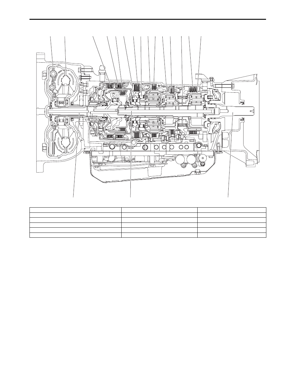
Automatic Transmission/Transaxle: 5A-3
1
2
3
4
5
6
7
8
9
10
11
12
13
14
15
16
17
18
I6JB01510046-01
1. Torque converter clutch (TCC)
7. 2nd brake
13. One-way No.3 clutch
2. Torque converter
8. One-way No.1 clutch
14. 1st and reverse brake
3. Direct clutch
9. Front planetary gear
15. Rear planetary
4. Reverse clutch
10. No.1 brake
16. Input shaft
5. Forward clutch
11. Middle planetary gear
17. Intermediate shaft
6. One-way No.2 clutch
12. No.2 brake
18. Output shaft
Нет комментариевНе стесняйтесь поделиться с нами вашим ценным мнением.
Текст