Suzuki Grand Vitara JB627. Service manual — part 14
1A-5 Engine General Information and Diagnosis:
Priority of freeze frame data
ECM has 4 frames where the freeze frame data can be stored. The first frame stores the freeze frame data of the
malfunction which was detected first. However, the freeze frame data stored in this frame is updated according to the
priority described below. (If malfunction as described in the upper square “1” below is detected while the freeze frame
data in the lower square “2” has been stored, the freeze frame data “2” will be updated by the freeze frame data “1”.)
In the 2nd through the 4th frames, the freeze frame data of each malfunction is stored in the order as the malfunction
is detected. These data are not updated.
Shown in the table below are examples of how freeze frame data are stored when two or more malfunctions are
detected.
—: No freeze frame data
Freeze frame data clearance
The freeze frame data is cleared at the same time as
clearance of DTC or Pending DTC.
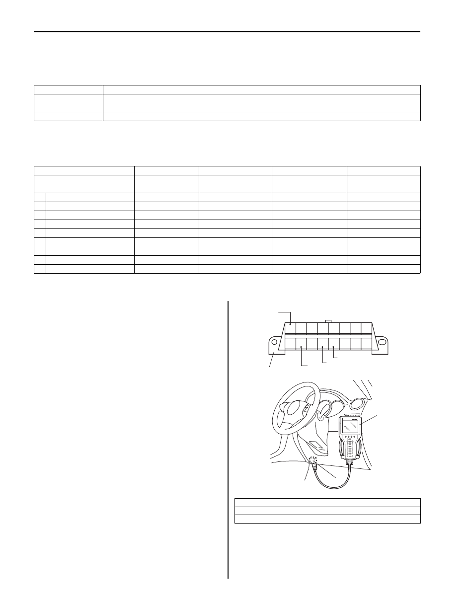
DLC (Data Link Connector)
DLC (1) is in compliance with SAE J1962 in the shape of
connector and pin assignment.
OBD serial data line (K line of ISO 9141) (3) is used for
SUZUKI scan tool or OBD generic scan tool to
communicate with ECM, SDM, BCM, TCM (A/T model),
4WD control module (if equipped) and ABS / ESP
®
control module.
Priority
Freeze frame data in frame 1
1
Freeze frame data at initial detection of malfunction among misfire detected (P0300 – P0306),
fuel system too lean (P0171, P0174) and fuel system too rich (P0172, P0175)
2
Freeze frame data when a malfunction other than those in “1” above is detected.
Frame
Frame 1
Frame 2
Frame 3
Frame 4
Malfunction detection order
Freeze frame
data
1st freeze frame
data
2nd freeze frame
data
3rd freeze frame
data
1 No malfunction detected
—
—
—
—
2 P0401 (Pending DTC)
P0401 data
P0401 data
—
—
3 No malfunction detected
P0401 data
P0401 data
—
—
4 No malfunction detected
—
—
—
—
5 P0111 (Pending DTC)
P0111 data
P0111 data
—
—
6
P0111
P0401 (Pending DTC)
P0111 data
P0111 data
P0401 data
—
7 P0300 (Pending DTC)
P0300 data
P0111 data
P0401 data
P0300 data
8 P0300
P0300 data
P0111 data
P0300 data
—
2. B + (Unswitched vehicle battery positive)
4. ECM ground (Signal ground)
5. Vehicle body ground (Chassis ground)
2
3
4
5
1
9
10
11
12
13
14
15
16
1
2
3
4
5
6
7
8
(A)
1
I5JB0C110020-02
Engine General Information and Diagnosis: 1A-6
Engine and Emission Control System Description
S6JB0B1101004
The engine and emission control system is divided into 4 major sub-systems: air intake system, fuel delivery system,
electronic control system and emission control system.
Air intake system includes air cleaner, mass air flow sensor, throttle body, intake manifold tuning valve and intake
manifold.
Fuel delivery system includes fuel pump, delivery pipe, fuel pressure regulator, fuel injectors, etc. Electronic control
system includes ECM, various sensors and controlled devices.
Emission control system includes EGR (if equipped), EVAP and PCV systems.
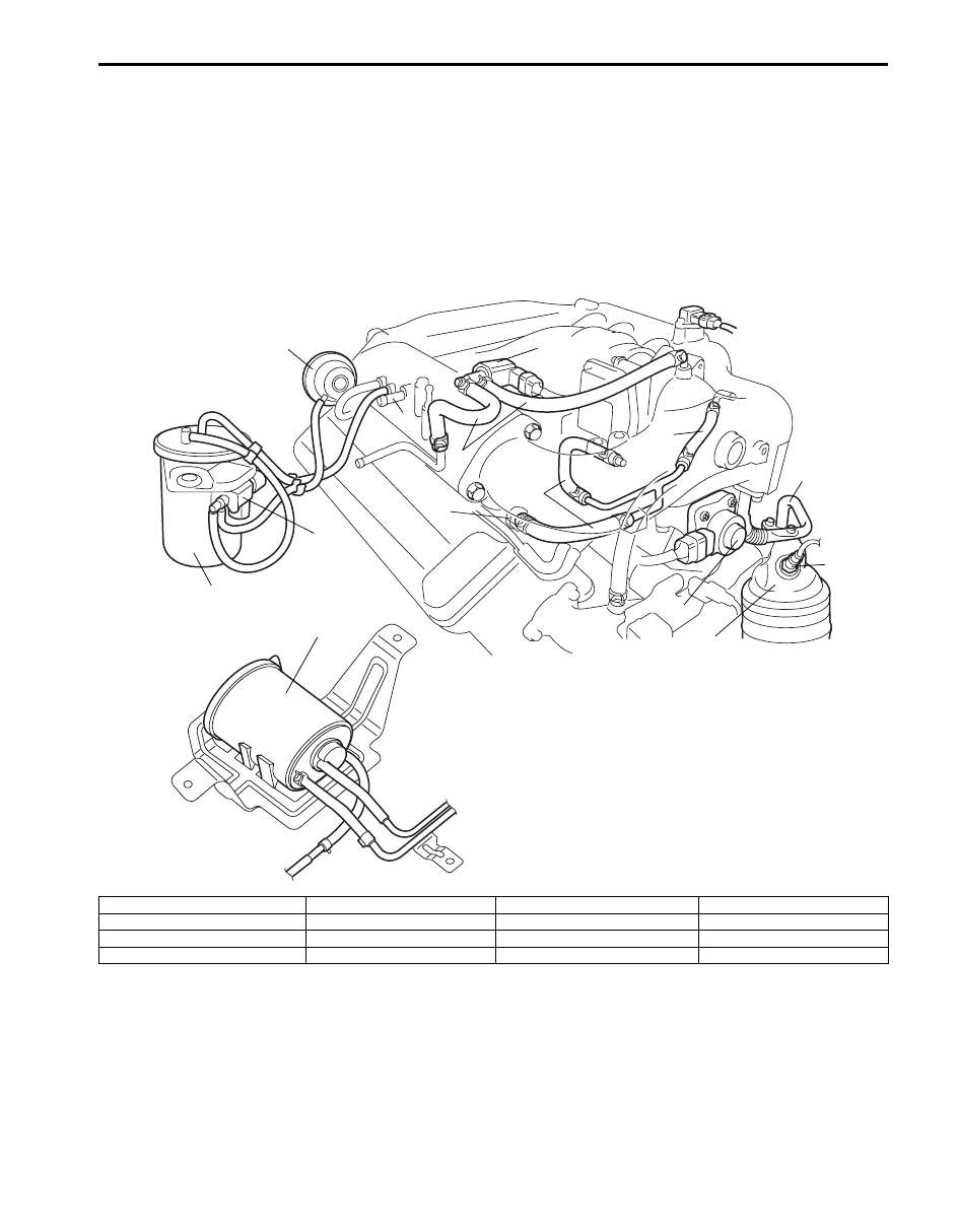
When hoses are disconnected and system components are removed for service, reinstall components properly, and
route and connect hoses correctly after service. Refer to the figure for proper routing of hoses.
8
12
1
4
5
3
6
10
11
7
7
2
9
13
I5JB0C110001-02
1: Brake booster hose pipe
5. A/F sensor
9. PCV valve
13. EVAP canister purge hose
2: EVAP canister purge valve
6. EGR valve (if equipped)
10. IMT valve
3: EGR pipe (if equipped)
7. PCV hose
11. IMT vacuum tank assembly
4: Exhaust manifold
8. EVAP canister
12. IMT vacuum solenoid valve
1A-7 Engine General Information and Diagnosis:
Air Intake System Description
S6JB0B1101005
The main components of the air intake system are air cleaner, air cleaner outlet hose, electric throttle body (for the
details, refer to “Electric Throttle Body System Description”.), IMT valve which adjusts the distributor pipe length of
intake manifold (for the details, refer to “IMT (Intake Manifold Tuning) System Description in Section 1D”.) and intake
manifold.
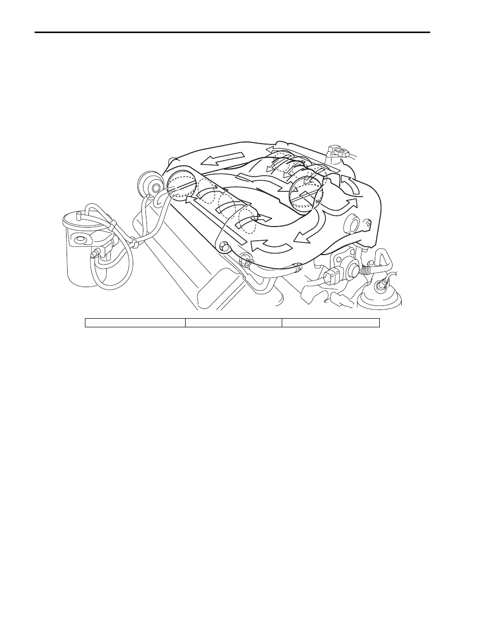
The air (by the amount corresponding to throttle valve opening and engine speed) is filtered by the air cleaner,
distributed by the intake manifold, and finally drawn into each combustion chamber. Electric throttle body is not
equipped with IAC valve for idle speed control. Idle speed control is done by the throttle actuator which opens / closes
the throttle valve. (For the details, refer to “Electric Throttle Body System Description”.)
Electric Throttle Body System Description
S6JB0B1101006
The Electric Throttle Body System consists of electric throttle body assembly, accelerator pedal position (APP) sensor
assembly, ECM and throttle actuator control relay.
Among them, assembly components are as follows.
• Electric throttle body assembly: Throttle valve, throttle actuator, 2 throttle position sensors.
• Accelerator pedal position (APP) sensor assembly: Accelerator pedal, 2 accelerator position sensors.
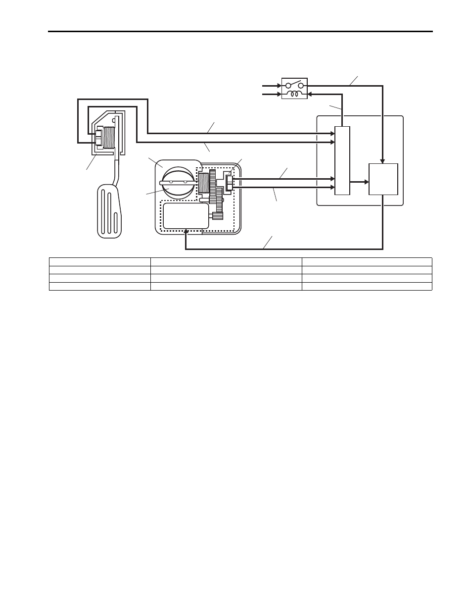
Operation Description
ECM (5) detects opening (depressed extent of pedal) of the accelerator pedal based on signal voltage of the
accelerator pedal position (APP) sensor (1) and using that data and engine operation condition, it calculates the
optimum throttle valve opening. On the other hand, it detects the throttle valve opening based on the signal voltage of
the throttle position sensor (3) included in the throttle body (2) and compares it with the above calculated optimum
throttle valve opening. When there is a difference between them, ECM controls the duty ratio (100% – 0%) according
to this difference to drive the throttle actuator (motor) (4) included in the throttle body. When there is no difference,
ECM controls the duty ratio to about 15% to maintain the throttle valve opening. In this way, the throttle valve (17) is
opened and closed to achieve the optimum throttle valve opening.
In this system, as the throttle position sensor and accelerator pedal position (APP) sensor have 2 sensors (main and
sub) each, highly accurate and highly reliable control and abnormality detection are assured. Also, when ECM detects
an abnormality in the system, it turns off the throttle actuator control relay (8) to stop controlling the throttle actuator.
When the throttle actuator control relay is turned off, the throttle valve is fixed at the opening of about 10
° from its
completely closed position (default opening) by the force of the return spring and open spring included in the throttle
body.
I6JB01110018-02
1. Throttle valve
2. IMT valve
3. Intake air
Engine General Information and Diagnosis: 1A-8
This throttle body is not equipped with IAC valve for idle speed control. Idle speed control is done by the throttle
actuator which opens/closes the throttle valve.
Description of Electric Throttle Body System Calibration
S6JB0B1101007
ECM calculates controlled opening of the throttle valve on the basis of the completely closed throttle valve position of
the electric throttle body system. The completely closed position data is saved in memory of ECM. However, the
completely closed position of the throttle valve of the electric throttle body system (signal voltage from throttle position
sensor when throttle is completely closed) differs one from the other depending on individual differences of the throttle
valve and throttle position sensor. As such individual differences must be taken into account for controlling the throttle
valve, it is necessary to register the completely closed throttle valve position data in ECM. When such data is
registered in ECM, it is saved in RAM (memory) of ECM and used as the base data for controlling the throttle valve.
This data is cleared, when any of the works described in “Precautions of Electric Throttle Body System Calibration” is
performed.
Also, after replacement of the throttle body and/or accelerator pedal position (APP) sensor assembly, the completely
closed position data in memory of ECM must be cleared once and a new one must be registered, or ECM cannot
judge the complete closure position properly.
For the procedure to register such data, refer to “Electric Throttle Body System Calibration in Section 1C”. (After the
completely closed position data is cleared, ECM, for the first time only, opens and closes the throttle valve for about 5
seconds after the ignition switch is turned ON position, for registration of the completely closed throttle valve position.
If the engine is started during this registration process, such symptom as “longer cranking time” or “slow rise of
revolution speed immediately after start-up” may occur. However, turning OFF the ignition switch once and restarting
will set correct registration.)
4
1
2
17
3
5
6
7
8
9
10
11
12
13
14
15
16
18
I4RS0B110007-02
6. CPU
11.
Accelerator pedal position (APP) sensor (main) signal
15. Drive signal of throttle actuator
7. Drive circuit of throttle actuator
12.
Accelerator pedal position (APP) sensor (sub) signal
16. Power supply of throttle actuator
9. From “THR MOT” fuse
13.
Throttle position sensor (main) signal
18. Control signal of throttle actuator control relay
10. From main relay
14.
Throttle position sensor (sub) signal
Нет комментариевНе стесняйтесь поделиться с нами вашим ценным мнением.
Текст