Suzuki Grand Vitara JB627. Service manual — part 99

1D-77 Engine Mechanical:
09926–58010
09944–36011
Bearing remover attachment
Steering wheel remover
Engine Lubrication System: 1E-1
Engine
Engine Lubrication System
General Description
Engine Lubrication Description
S6JB0B1501001
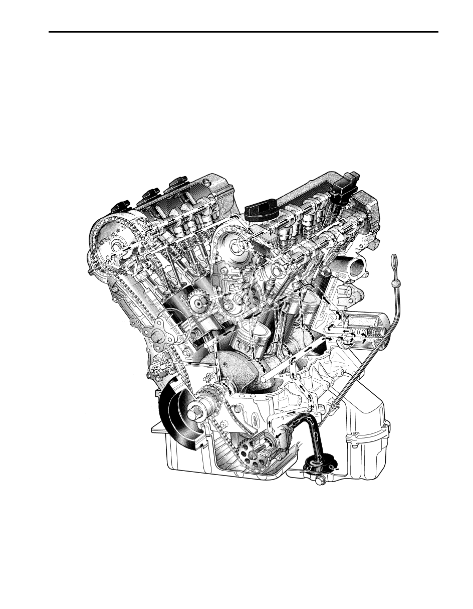
The oil pump is of a trochoid type, and mounted under the crankshaft. Oil is drawn up through the oil pump strainer
and passed through the pump to the oil filter. The filtered oil flows into 3 paths in cylinder block.
In one path, oil reaches the crankshaft main bearings. Oil from the crankshaft main bearings is supplied to the
connecting rod bearings by means of intersecting passages drilled in the crankshaft, and then injected from the big
end of connecting rod to lubricate piston, rings, and cylinder wall. In other paths oil goes up to the cylinder heads and
lubricates valves and camshafts, etc., after passing through the internal oil way of camshafts. An oil relief valve is
provided on the oil pump. This valve starts relieving oil pressure when the pressure exceeds the specified pressure.
I6JB01150001-02
1E-2 Engine Lubrication System:
Diagnostic Information and Procedures
Oil Pressure Check
S6JB0B1504001
NOTE
Prior to checking oil pressure, check the
followings.
• Oil level in oil pan
If oil level is low, add oil up to Full level
hole on oil level gauge.
• Oil quality
If oil is discolored or deteriorated, change
it.
For particular oil to be used, refer to
“Engine Oil and Filter Change in Section
0B”.
• Oil leaks
If leak is found, repair it.
1) Disconnect suction hose and discharge hose from A/
C compressor referring to “Compressor Assembly
Removal and Installation in Section 7B”.
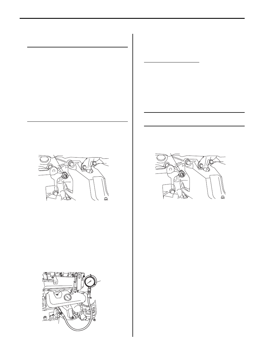
2) Remove oil pressure switch (1) from cylinder block.
3) Remove steering lower shaft assembly referring to
“Steering Lower Shaft Assembly Removal and
Installation in Section 6B”.
4) Install special tool (oil pressure gauge) to vacated
threaded hole.
Use oil pressure gauge (special tool (A)) with special
tool (B) instead of the steel adaptor supplied in
special tool (A).
Special tool
(A): 09915–77311
(B): 09915–76510
5) Start engine and warm it up to normal operating
temperature.
6) After warming up, raise engine speed to 3,000 rpm
and measure oil pressure.
Oil pressure specifications
250 kPa (2.5 kg/cm
2
, 36.25 psi) or more at 3,000
rpm
7) After checking oil pressure, stop engine and remove
oil pressure gauge.
8) Before reinstalling oil pressure switch, be sure to
wrap its screw threads with sealing tape and tighten
switch to specified torque.
NOTE
If sealing tape edge is bulged out from screw
threads of switch, cut it off.
Tightening torque
Oil pressure switch (a): 13 N·m (1.3 kgf-m, 9.5
lb-ft)
9) Connect suction hose and discharge hose to A/C
compressor referring to “Compressor Assembly
Removal and Installation in Section 7B”.
10) Start engine and check oil pressure switch for oil
leakage.
1
I6JB01150002-01
(A)
(B)
I6JB01150003-01
(a)
I6JB01150004-01
Engine Lubrication System: 1E-3
Repair Instructions
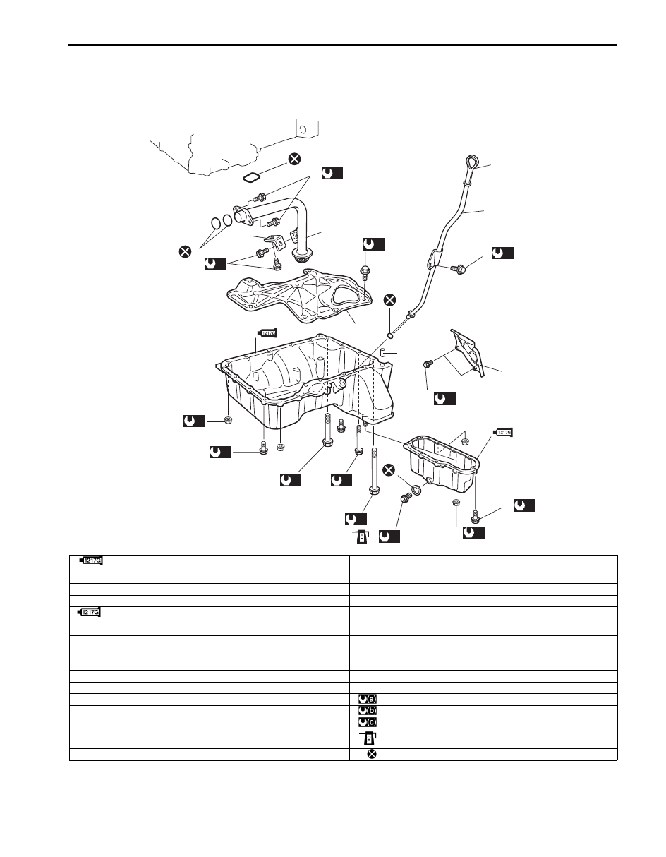
Oil Pan and Oil Pump Strainer Components
S6JB0B1506001
11
8
2
16
15
19
(a)
14
(c)
4
9
5
7
17
(a)
3
22
(a)
10
(a)
12
(a)
20
(a)
13
(a)
18
(a)
13
(a)
5
(b)
6
1
14
(c)
21
23
(a)
I6JB01150005-04
1. Upper oil pan
: Apply sealant 99000-31260 referring to “Oil Pan and Oil Pump
Strainer Removal and Installation”.
15. Oil level gauge
2. Oil pan baffle plate
16. Oil level gauge guide
3. Oil pan baffle plate bolt
17. Oil level gauge guide bolt
4. Lower oil pan
: Apply sealant 9900-31260 referring to “Oil Pan and Oil Pump
Strainer Removal and Installation”.
18. Lower oil pan nut
5. O-ring
19. Lower oil pan bolt
6. Drain plug
20. Upper oil pan mounting nut
7. Gasket
21. Dowel pin
8. Oil pump strainer
22. Drive plate cover (A/T) or clutch housing lower plate (M/T)
9. O-ring
23. Drive plate cover (A/T) bolt or clutch housing lower plate (M/T) bolt
10. Oil pump strainer bolt
: 11 N
⋅m (1.1 kgf-m, 8.0 lb-ft)
11. Oil pump strainer bracket
: 35 N
⋅m (3.5 kgf-m, 25.5 lb-ft)
12. Oil pump strainer bracket bolt
: 25 N
⋅m (2.5 kgf-m, 18.0 lb-ft)
13. Upper oil pan mounting bolt (M6)
: Apply engine oil to bolt thread
14. Upper oil pan mounting bolt (M8)
: Do not reuse.
Нет комментариевНе стесняйтесь поделиться с нами вашим ценным мнением.
Текст