Opel Meriva (2017 year). Instruction — part 12
182
Vehicle care
2. Detach bulb from the bulb holder
and replace it.
3. Insert the bulb holder into the
reflector and rotate clockwise.
Sidelight/Daytime running light
with LEDs
On another version sidelight and
daytime running lights are designed
as LEDs. In case of defective have
LEDs replaced by a workshop.
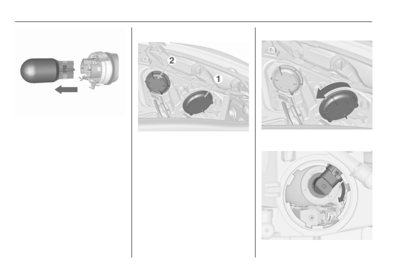
Adaptive forward lighting
Headlights have separate systems for
low beam and high beam 1 (outer
bulbs) and cornering light 2 (inner
bulbs).
Low beam/High beam
1. Rotate the cap 1 anticlockwise
and remove it.
-------------------------------------------------------------------------------------------------------------------------------------------------------------
Vehicle care
183
2. Rotate the bulb holder clockwise
to disengage. Withdraw the bulb
holder from the reflector.
3. Disengage the bulb holder from
the plug connector by pressing
the retaining lug.
4. Replace the bulb and connect
bulb holder with the plug
connector.
5. Insert the bulb holder, engaging
the two lugs into the reflector and
rotate anticlockwise to secure.
6. Fit the cap and rotate clockwise.
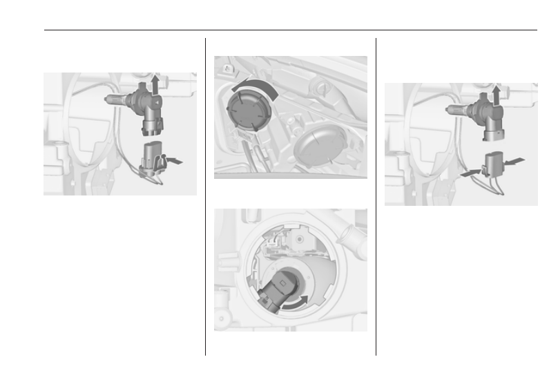
Cornering light
1. Rotate protective cover 2
anticlockwise and remove.
2. Rotate the bulb holder
anticlockwise to disengage.
Withdraw the bulb holder from the
reflector.
3. Disengage the bulb holder from
the plug connector by pressing
the retaining lugs.
4. Replace the bulb and connect
bulb holder with the plug
connector.
5. Insert the bulb holder, engaging
the two lugs into the reflector and
rotate clockwise to secure.
6. Fit the cap and rotate clockwise.
-------------------------------------------------------------------------------------------------------------------------------------------------------------
184
Vehicle care
Sidelight/Daytime running light
Sidelight and daytime running lights
are designed as LEDs. In case of
failure, have LEDs replaced by a
workshop.
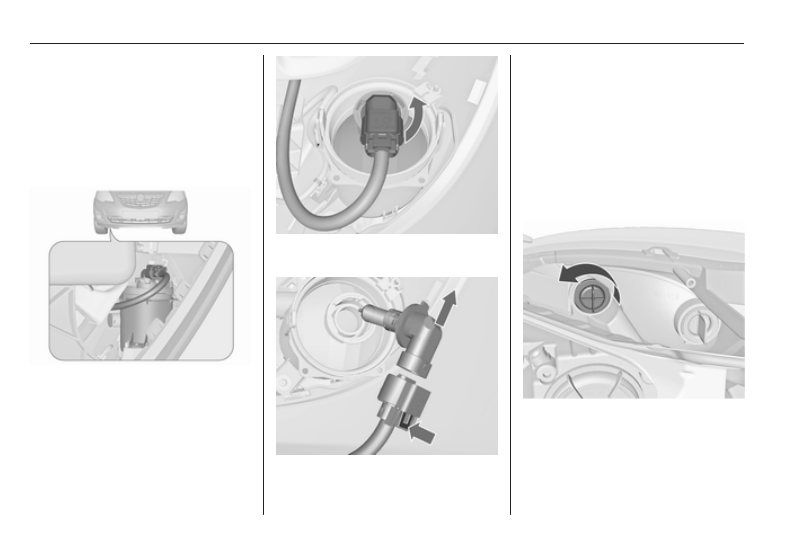
Fog lights
The bulbs are accessible from the
underside of the vehicle.
1. Turn the bulb holder anticlockwise
and remove it from the reflector.
2. Disengage the bulb holder from
the plug connector by pressing
the retaining lug.
3. Remove and replace the bulb
holder with bulb.
4. Attach the plug connector.
5. Insert the bulb holder into the
reflector.
6. Turn the bulb holder clockwise
and engage.
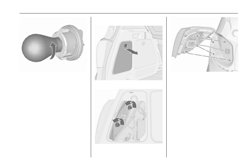
Front turn signal lights
1. Rotate the bulb holder
anticlockwise and remove it.
-------------------------------------------------------------------------------------------------------------------------------------------------------------
Vehicle care
185
2. Rotate bulb anticlockwise and
remove from bulb holder.
3. Replace bulb.
4. Insert the bulb holder into the
reflector and rotate clockwise.
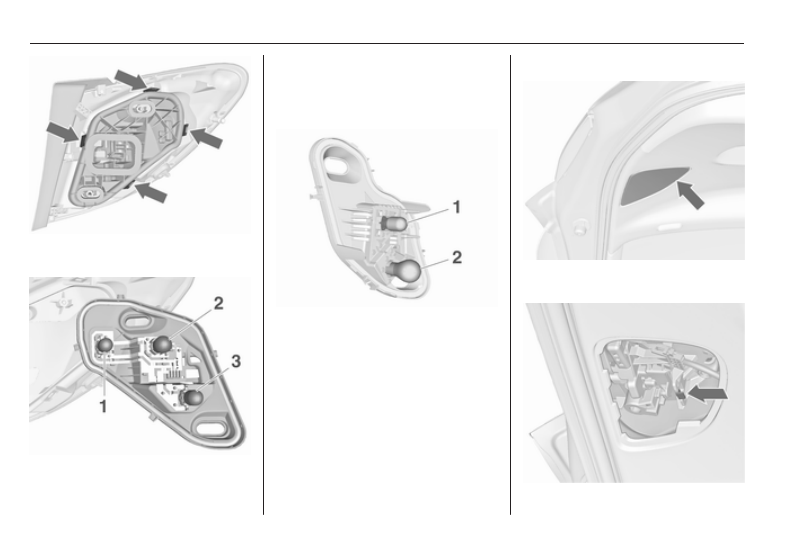
Tail lights
1. Release the cover and remove it.
2. Unscrew the two plastic securing
nuts from the inside by hand.
3. Carefully withdraw the light
assembly from retaining pins and
remove. Make sure that the cable
duct remains in position.
4. Detach the wiring plug from the
bulb carrier.
-------------------------------------------------------------------------------------------------------------------------------------------------------------
186
Vehicle care
5. Unlatch the four retaining lugs and
remove the bulb carrier.
6. Remove and replace the bulb.
Tail light and brake light (1)
Tail light (2)
Turn signal light (3)
Version with Light Emitting Diode
(LED):
Only brake light (1) and turn signal
light (2) can be changed.
7. Insert the bulb carrier into the tail
light assembly. Connect the
wiring plug. Fit light assembly
onto retaining pins and tighten the
securing nuts. Close the cover
and engage.
8. Switch on the ignition, operate
and check all lights.
Tail lights in the tailgate frame
1. Open the tailgate and remove the
cover with a screwdriver.
-------------------------------------------------------------------------------------------------------------------------------------------------------------
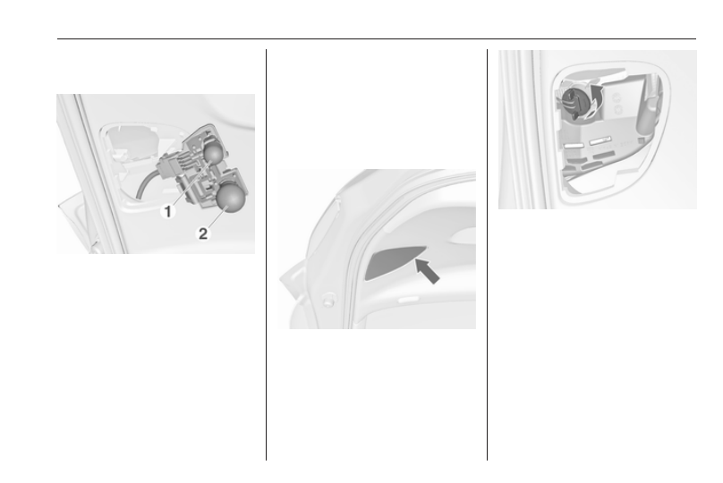
Vehicle care
187
2. Press the retaining lug and
remove the bulb carrier
downwards.
3. To replace the reverse light bulb
(1), remove and replace the bulb.
To replace the tail light/rear fog
light bulb (2), push the bulb
slightly into the socket, rotate
anticlockwise, remove and
replace the bulb.
4. Insert the bulb carrier into the
retainer.
5. Attach the cover.
6. Switch on the ignition, operate
and check all lights.
For replacing the tail light bulb and
reverse light bulb on the right side of
the tailgate frame, proceed in the
same way.
Version with Light Emitting Diode
(LED):
Only the reverse light bulb can be
changed.
1. Open the tailgate and remove the
cover with a screwdriver.
2. Rotate the bulb holder
anticlockwise to disengage.
Withdraw the bulb holder.
3. To replace the reverse light bulb,
push the bulb slightly into the
socket, rotate anticlockwise,
remove and replace the bulb.
4. Insert bulb holder and turn
clockwise.
5. Attach the cover.
-------------------------------------------------------------------------------------------------------------------------------------------------------------
188
Vehicle care
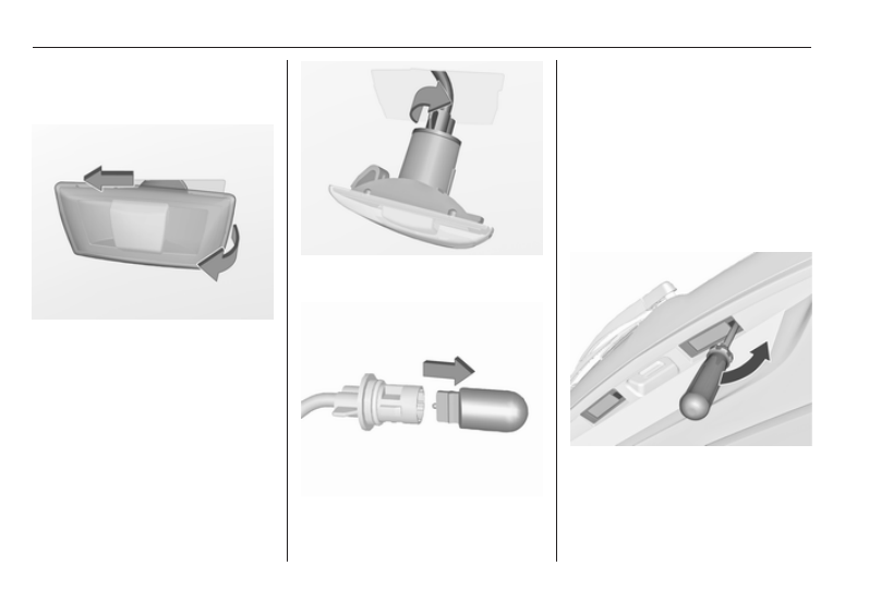
Side turn signal lights
To replace bulb, remove lamp
housing:
1. On left vehicle side, slide lamp to
the front and remove it out of the
front wing with the rear end.
On right vehicle side, slide lamp to
the rear and remove it out of the
front wing with the front end.
2. Turn bulb holder anticlockwise
and remove from housing.
3. Pull bulb from bulb holder and
replace it.
4. Insert bulb holder and turn
clockwise.
5. On left side: insert front end into
front wing, slide forward and insert
rear end.
On right side: insert rear end into
front wing, slide rearward and
insert front end.
Number plate light
1. Insert screwdriver in recess of the
cover, press to the side and
release spring.
-------------------------------------------------------------------------------------------------------------------------------------------------------------
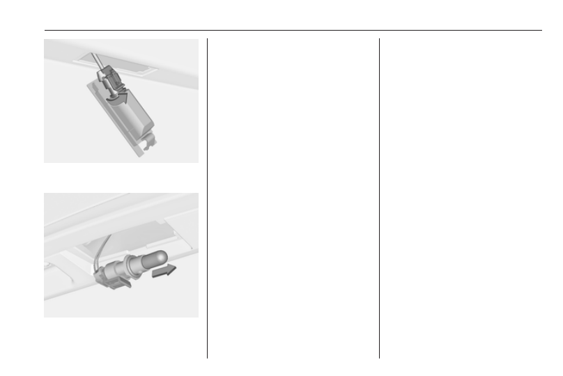
Vehicle care
189
2. Remove lamp downwards, taking
care not to pull on the cable.
3. Remove bulb holder from lamp
housing by turning anticlockwise.
4. Pull bulb from bulb holder and
replace it.
5. Insert bulb holder into lamp
housing and turn clockwise.
6. Insert lamp into bumper and let
engage.
Interior lights
Courtesy light, reading lights
Have bulbs replaced by a workshop.
Load compartment light
Have bulbs replaced by a workshop.
Instrument panel
illumination
Have bulbs replaced by a workshop.
Electrical system
Fuses
Data on the replacement fuse must
match the data on the defective fuse.
There are three fuse boxes in the
vehicle:
● in the front left of the engine
compartment
● in left-hand drive vehicles, in the
interior behind the storage
compartment, or, in right-hand
drive vehicles, behind the
glovebox
● behind a cover on the left side of
the load compartment
Before replacing a fuse, turn off the
respective switch and the ignition.
A blown fuse can be recognized by its
melted wire. Do not replace the fuse
until the cause of the fault has been
remedied.
Some functions are protected by
several fuses.
Fuses may also be inserted without
existence of a function.
-------------------------------------------------------------------------------------------------------------------------------------------------------------
190
Vehicle care
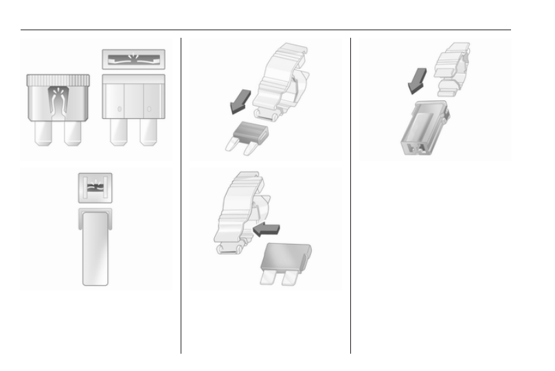
Fuse extractor
A fuse extractor may be located in the
fuse box in the engine compartment.
Place the fuse extractor on the
various types of fuse from the top or
side, and withdraw fuse.
-------------------------------------------------------------------------------------------------------------------------------------------------------------
Vehicle care
191
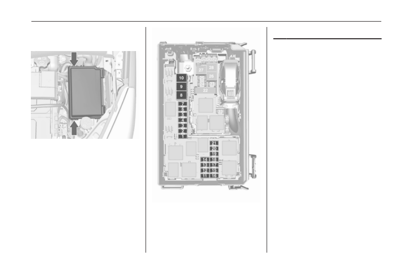
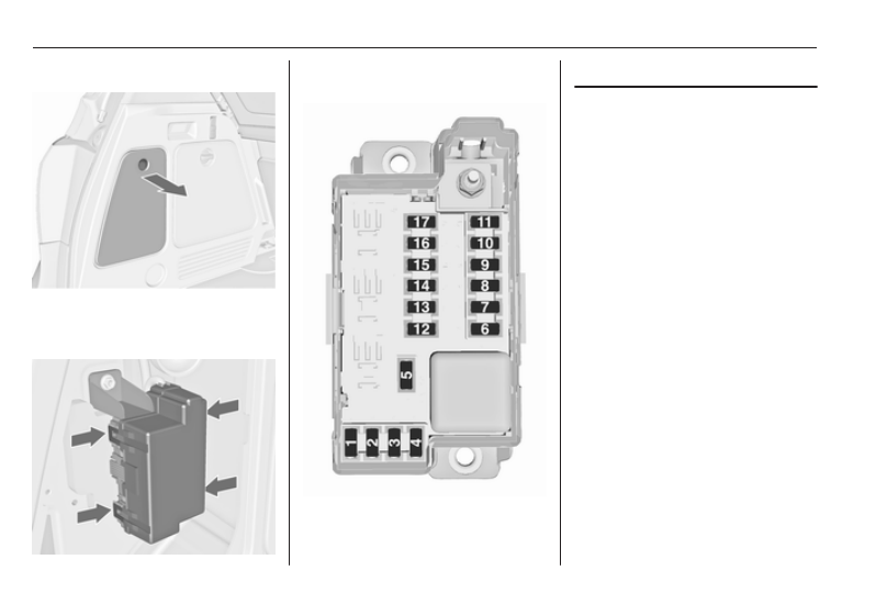
Engine compartment fuse
box
The fuse box is in the front left of the
engine compartment.
Disengage the cover, lift it upwards
and remove.
After having changed defective fuses
close the fuse box cover and press
until it engages.
If the fuse box cover is not closed
correctly, malfunctions may occur.
No. Circuit
1
Starter
2
–
3
Fuel filter/Cooling
4
Horn
5
Terminal 30
6
Engine control module/Trans‐
mission control unit
7
Fog light
8
Engine cooling
9
Engine cooling
10 Vacuum pump
11 Ignition/Preheating
12 Headlamp levelling
13 Air conditioning system/
Terminal 15
14 Transmission control unit
15 High beam right
16 High beam left
-------------------------------------------------------------------------------------------------------------------------------------------------------------
192
Vehicle care
No. Circuit
17 Engine control module
18 Engine control module/
Terminal 15
19 Airbag
20 Engine control module
21 Engine control module/
Terminal 87
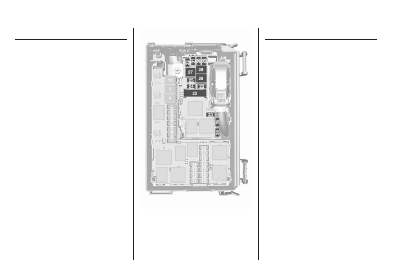
No. Circuit
22 Electrical parking brake
23 Tyre repair kit
24 Fuel pump
25 ABS
26 Heated rear window
27 ABS
28 Interior fan
29 Cigarette lighter
30 Air conditioning system
31 Front power window, left
32 Front power window, right
33 Mirror heating
34 ABS
35 Airbag
-------------------------------------------------------------------------------------------------------------------------------------------------------------
Vehicle care
193
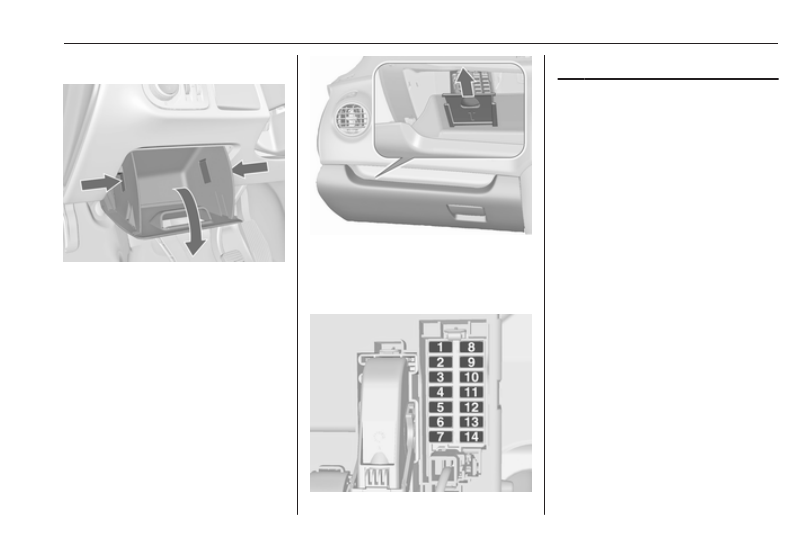
Instrument panel fuse box
In left-hand drive vehicles, the fuse
box is behind the storage
compartment in the instrument panel.
Open compartment, compress the
locking tabs, fold compartment down
and remove.
In right-hand drive vehicles, the fuse
box is located behind a cover in the
glovebox. Open the glovebox, pull
cover upwards and remove.
No. Circuit
1
Radio
2
Display/Instrument/Telephone
3
Radio
4
Ignition switch/Immobiliser
5
Windscreen washer/Rear
screen washer
6
Central locking system/Tailgate
7
Central locking system
8
Display/Instrument/Telephone
9
Heated steering wheel
10 Rear left door unlocking
11 Rear right door unlocking
12 Courtesy light
13 Rain sensor/Interior mirror/
Exterior mirrors
14 –
-------------------------------------------------------------------------------------------------------------------------------------------------------------
194
Vehicle care
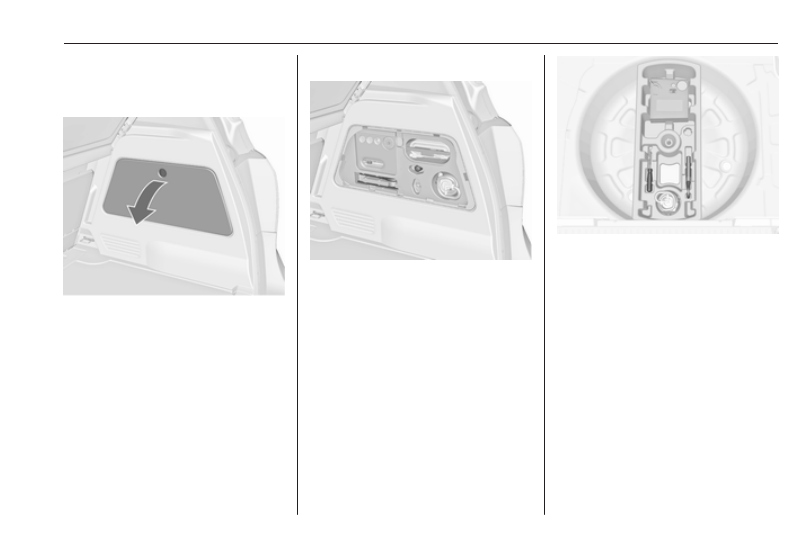
Load compartment fuse box
The fuse box is on the left side of the
load compartment behind a cover.
Remove the cover.
Disengage the four retaining lugs and
remove the cover.
No. Circuit
1
Adaptive forward lighting
2
–
3
–
4
–
5
–
6
Right rear power window
7
Adaptive forward lighting
8
Trailer module/Trailer socket
9
Left seat lumbar support
10 Left rear power window
11 Park assist
12 Electrical sunblind
13 –
14 Heated front seats
15 Trailer module
16 Right seat lumbar support
17 –
-------------------------------------------------------------------------------------------------------------------------------------------------------------
Vehicle care
195
Vehicle tools
Tools
To open the compartment, disengage
the cover and open it, or, depending
on the version, lift the floor cover.
Vehicles with tyre repair kit
Variant 1: The vehicle tools are in the
right-hand compartment in the load
compartment, together with the tyre
repair kit.
Variant 2: The vehicle tools are in the
compartment under the floor cover in
the load compartment, together with
the tyre repair kit.
-------------------------------------------------------------------------------------------------------------------------------------------------------------
196
Vehicle care
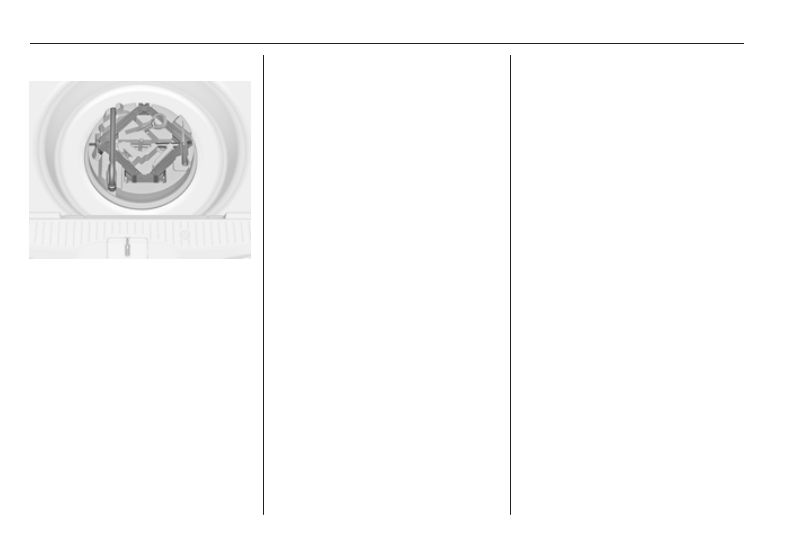
Vehicles with spare wheel
The jack and the vehicle tools are in
the spare wheel well in the load
compartment.
Wheels and tyres
Tyre condition, wheel condition
Drive over edges slowly and at right
angles if possible. Driving over sharp
edges can cause tyre and wheel
damage. Do not trap tyres on the kerb
when parking.
Regularly check the wheels for
damage. Seek the assistance of a
workshop in the event of damage or
unusual wear.
Winter tyres
Winter tyres improve driving safety at
temperatures below 7 °C and should
therefore be fitted on all wheels.
In accordance with country-specific
regulations, affix the speed sticker in
the driver's field of view.
Tyre designations
E.g. 195/65 R 15 91 H
195 : tyre width, mm
65 : cross-section ratio (tyre height
to tyre width), %
R
: belt type: Radial
RF : type: RunFlat
15 : wheel diameter, inches
91 : load index e.g. 91 is equivalent
to 615 kg
H
: speed code letter
Speed code letter:
Q : up to 160 km/h
S : up to 180 km/h
T : up to 190 km/h
H : up to 210 km/h
V : up to 240 km/h
W : up to 270 km/h
Choose a tyre appropriate for the
maximum speed of your vehicle.
The maximum speed is achievable at
kerb weight with driver (75 kg) plus
125 kg payload. Optional equipment
could reduce the maximum speed of
the vehicle.
Performance 3 230.
Directional tyres
Directional tyres must be mounted so
that they rotate in the correct
direction. The proper rotation
direction is indicated by a symbol
(e.g. an arrow) on the sidewall.
-------------------------------------------------------------------------------------------------------------------------------------------------------------
Vehicle care
197
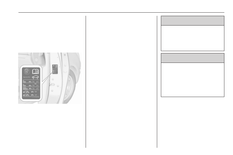
Tyre pressure
Check the pressure of cold tyres at
least every 14 days and before any
long journey. Do not forget the spare
wheel. This also applies to vehicles
with tyre pressure monitoring system.
Unscrew the valve cap.
Tyre pressure 3 235.
The tyre pressure information label
on the right door frame indicates the
original equipment tyres and the
correspondent tyre pressures.
The tyre pressure data refers to cold
tyres. It applies to summer and winter
tyres.
Always inflate the spare tyre to the
pressure specified for full load.
The ECO tyre pressure serves to
achieve the smallest amount of fuel
consumption possible.
Incorrect tyre pressures will impair
safety, vehicle handling, comfort and
fuel economy and will increase tyre
wear.
Tyre pressures differ depending on
various options. For the correct tyre
pressure value, follow the procedure
below:
1. Identify the engine identifier code.
Engine data 3 228.
2. Identify the respective tyre.
The tyre pressure tables show all
possible tyre combinations 3 235.
For the tyres approved for your
vehicle, refer to the EEC Certificate of
Conformity provided with your vehicle
or other national registration
documents.
The driver is responsible for correct
adjustment of tyre pressure.
9 Warning
If the pressure is too low, this can
result in considerable tyre warm-
up and internal damage, leading to
tread separation and even to tyre
blow-out at high speeds.
9 Warning
For specific tyres the
recommended tyre pressure as
shown in the tyre pressure table
may exceed the maximum tyre
pressure as indicated on the tyre.
Never exceed the maximum tyre
pressure as indicated on the tyre.
If the tyre pressure must be reduced
or increased on a vehicle with tyre
pressure monitoring system, switch
off ignition.
Temperature dependency
The tyre pressure depends on the
temperature of the tyre. During
driving, tyre temperature and
pressure increase. Tyre pressure
-------------------------------------------------------------------------------------------------------------------------------------------------------------
Нет комментариевНе стесняйтесь поделиться с нами вашим ценным мнением.
Текст