Opel Meriva (2017 year). Instruction — part 4
54
Seats, restraints
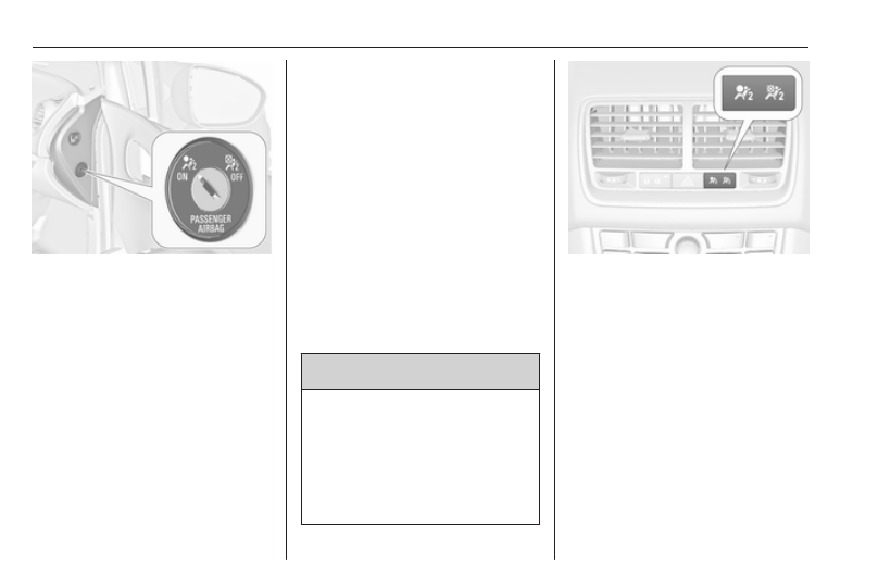
The front passenger airbag system
can be deactivated via a key-
operated switch on the right side of
the instrument panel.
Use the ignition key to choose the
position:
*
: front passenger airbag is
deactivated and will not inflate in
the event of a collision. Control
indicator * illuminates
continuously in the centre
console. A child restraint
system can be installed in
accordance with the chart Child
restraint installation locations
allowed to occupy the front
passenger seat
V
: front passenger airbag is active.
A child restraint system must
not be installed
9 Danger
Risk of fatal injury for a child using
a child restraint system on a seat
with activated front passenger
airbag.
Risk of fatal injury for an adult
person on a seat with deactivated
front passenger airbag.
If the control indicator V illuminates
for approx. 60 seconds after the
ignition is switched on, the front
passenger airbag system will inflate
in the event of a collision.
If both control indicators are
illuminated at the same time, there is
a system failure. The status of the
system is not discernible, therefore
no person is allowed to occupy the
front passenger seat. Contact a
workshop immediately.
Change status only when the vehicle
is stationary with the ignition off.
Status remains until the next change.
-------------------------------------------------------------------------------------------------------------------------------------------------------------
Seats, restraints
55
Control indicator for airbag
deactivation 3 95.
Child restraints
Child restraint systems
We recommend the Opel child
restraint system DUO which is
tailored specifically to the vehicle.
When using the Opel child restraint
system DUO, move the rear outboard
seats into position 2 3 42. We
recommend fastening the Opel child
restraint system DUO by using the
following securing systems in
combination:
ISOFIX
Three-point seat belt
Top-Tether
-------------------------------------------------------------------------------------------------------------------------------------------------------------
56
Seats, restraints
When a child restraint system is being
used, pay attention to the following
usage and installation instructions
and also those supplied with the child
restraint system.
Always comply with local or national
regulations. In some countries, the
use of child restraint systems is
forbidden on certain seats.
9 Warning
If using a child restraint system on
the front passenger seat, the
airbag system for the front
passenger seat must be
deactivated; if not, the triggering of
the front airbag poses a risk of fatal
injury to the child.
This is especially the case if
rearfacing child restraint systems
are used on the front passenger
seat.
Airbag deactivation 3 53,
Airbag label 3 49.
Selecting the right system
The rear seats are the most
convenient location to fasten a child
restraint system.
Children should travel facing
rearwards in the vehicle as long as
possible. This makes sure that the
child's backbone, which is still very
weak, is under less strain in the event
of an accident.
Suitable are restraint systems that
comply with valid UN ECE
regulations. Check local laws and
regulations for mandatory use of child
restraint systems.
Ensure that the child restraint system
to be installed is compatible with the
vehicle type.
Ensure that the mounting location of
the child restraint system within the
vehicle is correct, see following
tables.
Allow children to enter and exit the
vehicle only on the side facing away
from the traffic.
When the child restraint system is not
in use, secure the seat with a seat belt
or remove it from the vehicle.
Note
Do not stick anything on the child
restraint systems and do not cover
them with any other materials.
A child restraint system which has
been subjected to stress in an
accident must be replaced.
-------------------------------------------------------------------------------------------------------------------------------------------------------------
Seats, restraints
57
Child restraint installation locations
Permissible options for fitting a child restraint system
Weight and age class
On front passenger seat
On rear outboard seats On rear centre seat
activated airbag deactivated airbag
Group 0: up to 10 kg
or approx. 10 months
X
U
1
U
2
U
3
Group 0+: up to 13 kg
or approx. 2 years
X
U
1
U
2
U
3
Group I: 9 to 18 kg
or approx. 8 months to 4 years
X
U
1
U
2
U
3
Group II: 15 to 25 kg
or approx. 3 to 7 years
X
X
U
2
U
3
Group III: 22 to 36 kg
or approx. 6 to 12 years
X
X
U
2
U
3
1
: if the child restraint system is being secured using a three-point seat belt, move seat height adjustment to uppermost
position and ensure that vehicle seat belt runs forwards from the upper anchorage point. Adjust seat backrest
inclination as far as necessary to a vertical position to ensure that the belt is tight on the buckle side.
2
: only if outboard seats are in position 1 or 2, 3 42.
3
: only if outboard seats are flush with the centre seat (position 2, 3 42).
U : universal suitability in conjunction with three-point seat belt.
X : no child restraint system permitted in this weight and age class.
-------------------------------------------------------------------------------------------------------------------------------------------------------------

58
Seats, restraints
Permissible options for fitting an ISOFIX child restraint system
Weight class
Size class Fixture
On front passenger
seat
On rear outboard seats
On rear centre
seat
Group 0: up to 10 kg
or approx. 10 months
E
ISO/R1 X
IL
1
X
Group 0+: up to 13 kg
or approx. 2 years
E
ISO/R1 X
IL
1
X
D
ISO/R2 X
IL
1
X
C
ISO/R3 X
IL
1
X
Group I: 9 to 18 kg
or approx. 8 months to 4 years
D
ISO/R2 X
IL
1
X
C
ISO/R3 X
IL
1
X
B
ISO/F2 X
IL
1
, IUF
1, 2
X
B1
ISO/F2X X
IL
1
, IUF
1, 2
X
A
ISO/F3 X
IL
1
, IUF
1, 2
X
Group II: 15 to 25 kg
or approx. 3 to 7 years
X
IL
1
X
Group III: 22 to 36 kg
or approx. 6 to 12 years
X
IL
1
X
-------------------------------------------------------------------------------------------------------------------------------------------------------------
Seats, restraints
59
IL : suitable for particular ISOFIX restraint systems of the 'specific-vehicle', 'restricted' or 'semi-universal' categories.
The ISOFIX restraint system must be approved for the specific vehicle type.
IUF : suitable for ISOFIX forward-facing child restraint systems of universal category approved for use in this weight class.
X
: no ISOFIX child restraint system approved in this weight class.
1
: only if outboard seats are in position 1 or 2, 3 42.
2
: only for Opel child restraint system DUO: If the seat is secured as recommended 3 55, the outboard seats must be
in position 2 3 42.
ISOFIX size class and seat device
A – ISO/F3
: forward-facing child restraint system for children of maximum size in the weight class 9 to 18 kg.
B – ISO/F2
: forward-facing child restraint system for smaller children in the weight class 9 to 18 kg.
B1 – ISO/F2X : forward-facing child restraint system for smaller children in the weight class 9 to 18 kg.
C – ISO/R3
: rear-facing child restraint system for children of maximum size in the weight class up to 18 kg.
D – ISO/R2
: rear-facing child restraint system for smaller children in the weight class up to 18 kg.
E – ISO/R1
: rear-facing child restraint system for young children in the weight class up to 13 kg.
-------------------------------------------------------------------------------------------------------------------------------------------------------------
60
Seats, restraints
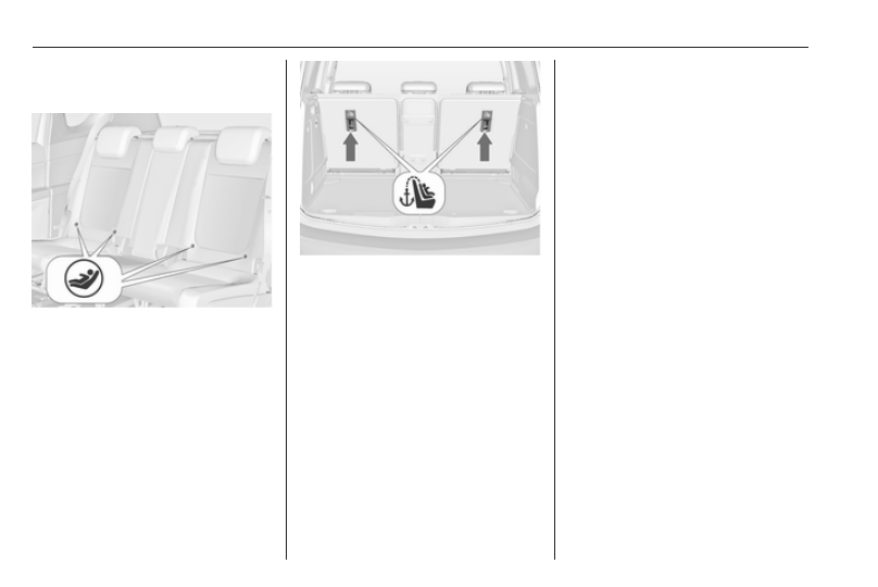
ISOFIX child restraint
systems
Fasten vehicle-approved ISOFIX
child restraint systems to the ISOFIX
mounting brackets. Specific vehicle
ISOFIX child restraint system
positions are marked in the table by
IL.
ISOFIX mounting brackets are
indicated by a label on the backrest.
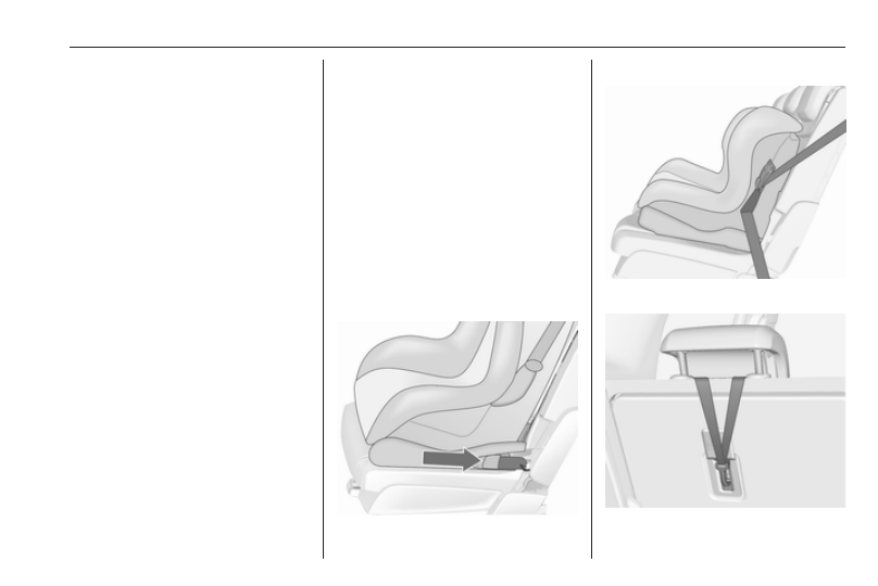
Top-tether fastening eyes
Top-Tether fastening eyes are
marked with the symbol : for a child
seat.
In addition to the ISOFIX mounting,
fasten the Top-Tether strap to the
Top-Tether fastening eyes. The strap
must run between the two guide rods
of the head restraint.
ISOFIX child restraint systems of
universal category positions are
marked in the table by IUF.
-------------------------------------------------------------------------------------------------------------------------------------------------------------
Storage
61
Storage
Storage compartments . . . . 61
Glovebox . . . . . . . . ... 61
Cupholders . . . . . . . . 61
Front storage . . . . . . . . 63
Underseat storage . . . . . . 63
Armrest storage . . . . . . . 63
Rear carrier system . . . . ... 64
Load compartment . . . . . ... 73
Rear storage . . . . . . . .. 74
Load compartment cover . . ... 74
Rear floor storage cover . . . 75
Lashing eyes . . . . . . . . 76
Safety net . . . . . . . . .. 76
Folding tray . . . . . . . . 78
Warning triangle . . . . . . 78
First aid kit . . . . . . . . . 78
Roof rack system . . . . . . . 79
Roof rack . . . . . . . . ... 79
Loading information . . . . . . 79
Storage compartments
9 Warning
Do not store heavy or sharp
objects in the storage
compartments. Otherwise, the
storage compartment lid could
open and vehicle occupants could
be injured by objects being thrown
around in the event of hard
braking, a sudden change in
direction or an accident.
Glovebox
The glovebox features a pen holder,
a coin holder and an adapter for the
locking wheel bolts.
Inside the glovebox there is a
compartment for the Owner's Instruction.
Pull the lug to open the compartment.
The glovebox should be closed whilst
driving.
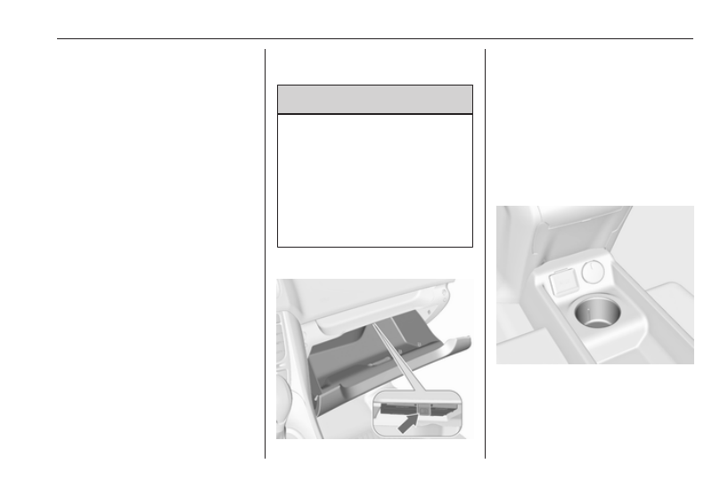
Cupholders
A cupholder is located in the centre
console.
-------------------------------------------------------------------------------------------------------------------------------------------------------------
62
Storage
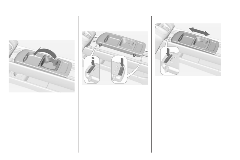
Detachable cupholder
A cupholder can be attached either to
the upper or lower guide rails in the
front console.
Fold the frame out of its initial position
before using.
Note
If the cupholder is installed in the
lower guide rail and the detachable
armrest in the upper guide rail,
ensure that the frame is folded back
into the initial position before moving
any of the parts.
Otherwise, the armrest and the
cupholder might be damaged while
moving them one above the other.
Armrest 3 40.
Installing cupholder
Press the buttons at the front and rear
and insert the guide pins into the
upper or lower guide rails. The front
button must be pressed firmly.
Release the buttons and move the
cupholder until it engages audibly.
Note
Install the cupholder in the direction
as shown in the illustration.
Otherwise the cupholder may not
engage properly.
Moving cupholder
Press the front button slightly and
move the cupholder to the desired
position. Release the button and
move the cupholder until it engages
audibly.
Removing cupholder
Press the buttons at the front and rear
and remove the cupholder. The front
button must be pressed firmly.
Cupholder on armrest adapter
A further cupholder is integrated to
the armrest adapter of the rear centre
seat.
-------------------------------------------------------------------------------------------------------------------------------------------------------------
Storage
63
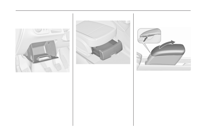
Front storage
A storage compartment is located
next to the steering wheel.
Underseat storage
Lift drawer at recessed edge and pull
out. Maximum load: 3 kg. To close,
push the drawer in and engage.
Armrest storage
Storage in the detachable armrest
Push button and fold the armrest lid
upwards. The armrest contains a
storage compartment.
The armrest can also be installed on
the folded centre rear seat 3 43.
-------------------------------------------------------------------------------------------------------------------------------------------------------------
64
Storage
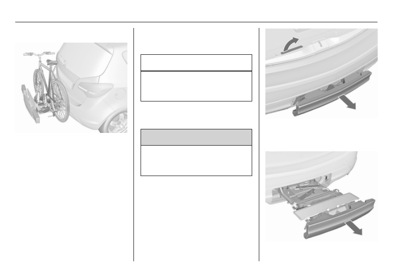
Rear carrier system
The rear carrier system (Flex-Fix
system) allows bicycles to be
attached to a pull-out carrier
integrated into the vehicle floor. The
transportation of other objects is not
permitted.
The maximum load of the rear carrier
system is 40 kg. The maximum load
per bicycle is 20 kg.
The wheelbase of a bicycle must not
exceed 1.2 metres. Otherwise the
secure fastening of a bicycle is not
possible.
If not in use, the rear carrier system
can be slid back into the vehicle floor.
There must not be any objects on the
bicycles that could become loose
during transportation.
Caution
Do not attach bicycles with carbon
pedal cranks to bicycle carriers.
The bicycles may get damaged.
Extending
Open the tailgate.
9 Warning
No-one should be in the extension
zone of the rear carrier system,
risk of injury.
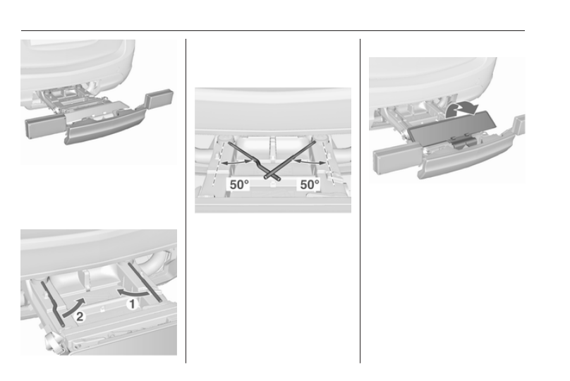
Pull release lever up. The system
disengages and travels quickly out of
the bumper.
-------------------------------------------------------------------------------------------------------------------------------------------------------------
Storage
65
Completely pull out the rear carrier
system until you hear it engage.
Ensure that it is not possible to push
in the rear carrier system without
pulling the release lever again
9 Warning
It is only permissible to fit objects
to the rear carrier system if the
system has been correctly
engaged. If the rear carrier system
will not engage correctly, do not fit
objects to the system and slide the
system back. Seek the assistance
of a workshop.
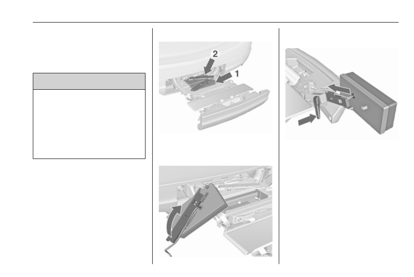
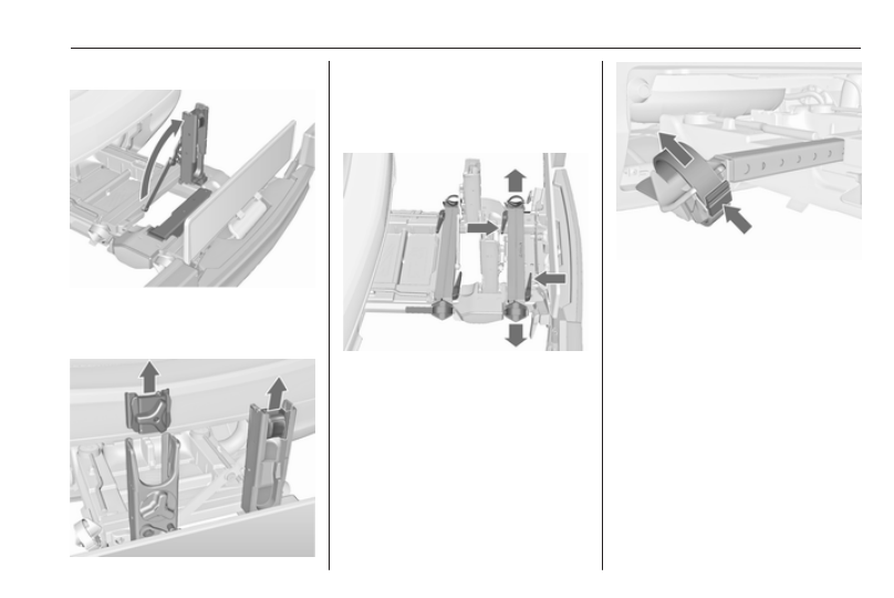
Install the tail lamps
First remove the rear tail lamp (1),
then the front (2) tail lamp from the
recesses.
Open out the lamp support on the
back of the tail lamp completely.
Push the clamping lever down and
push the lamp support into the
retainer until it engages.
Perform this procedure for both tail
lamps.
-------------------------------------------------------------------------------------------------------------------------------------------------------------
66
Storage
Check the cable and lamp position to
make sure these are correctly
installed and are securely located.
Lock the rear carrier system
Swivel the right clamping lever (1)
first, followed by the left clamping
lever (2), until a resistance is
noticeable.
The rear carrier system is locked
when the clamping levers are
swivelled by approx. 50°. Otherwise
safe functionality is not guaranteed.
Note
Close the tailgate.
Unfold the number plate holder
Unfold the holder for the number
plate.
Affix the number plate before first
usage of the rear carrier system.
-------------------------------------------------------------------------------------------------------------------------------------------------------------
Storage
67
Unfold pedal crank recesses
Fold one or both pedal crank
recesses upwards until the diagonal
support engages.
Remove the pedal crank mounts from
the pedal crank recesses.
Adapting the rear carrier system
to a bicycle
Press the release lever and withdraw
the wheel recesses.
Push the release lever on the strap
retainer and remove the strap
retainer.
-------------------------------------------------------------------------------------------------------------------------------------------------------------
68
Storage
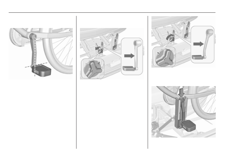
Prepare the bicycle for
attachment
Note
The maximum width for the pedal
crank is 38.3 mm and the maximum
depth is 14.4 mm.
Rotate the left pedal (without a chain
cog) vertically downwards. The pedal
on the left pedal crank must be
horizontal.
The front bicycle must have its front
wheel facing left.
The rear bicycle must have its front
wheel facing right.
Attaching a bicycle to the rear
carrier system
With the rotary lever on the pedal
crank recess, roughly adapt the
adjustable pedal crank unit to the
protrusion of the pedal crank.
If the bicycle has straight pedal
cranks, unscrew the pedal crank unit
completely (position 5).
If the bicycle has curved pedal
cranks, screw in the pedal crank unit
all the way (position 1).
-------------------------------------------------------------------------------------------------------------------------------------------------------------
Storage
69
Put on the bicycle. The pedal crank
here must be placed in the pedal
crank recess opening as shown in the
illustration.
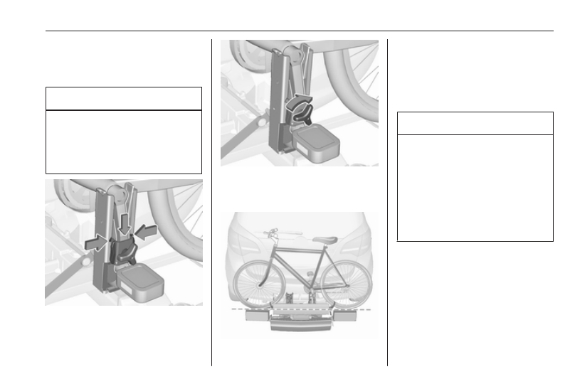
Caution
Make sure that the pedal does not
touch the surface of the rear end
carrier. Otherwise the crankset
might be damaged during the
transport.
Insert pedal crank mount into outer
rail of each pedal crank recess from
above and slide downwards until at
least underneath the notching.
Attach the pedal crank by rotating the
attachment screw on the pedal crank
mount.
Place the wheel recesses so that the
bicycle is roughly horizontal. Here,
the distance between the pedals and
the tailgate should be at least 5 cm.
Both bicycle tyres must be in the
wheel recesses.
Caution
Make sure to pull out the wheel
recesses as far as necessary to
have both bicycle tyres placed in
the recesses. Otherwise a
horizontal mounting of the bicycle
is not ensured. Disregard could
lead to damage of the bicycle
wheels caused by hot exhaust
fumes.
-------------------------------------------------------------------------------------------------------------------------------------------------------------
Нет комментариевНе стесняйтесь поделиться с нами вашим ценным мнением.
Текст