Opel Frontera UBS. Service manual — part 481

6E–54
4JX1–TC ENGINE DRIVEABILITY AND EMISSIONS
ECM Diagnostic Trouble Codes
The following table lists the diagnostic trouble codes
supported a Tech 2 and to flash.If any DTCs not listed
here are displayed by a Tech 2, the Tech 2 data may be
faulty; notify the Tech 2 manufacturer of any DTCs
displayed that are not included in the following table.
ECM Diagnostic Trouble Codes
DTC
using a
Tech 2
Flash DTC
Description
MIL
P0107
34
MAP Sensor Low Voltage
ON
P0108
34
MAP Sensor High Voltage
ON
P0112
23
Intake Air temp Sensor Low Voltage
ON
P0113
23
Intake Air temp Sensor High Voltage
ON
P0117
14
Engine Coolant Temp Sensor Low Voltage
ON
P0118
14
Engine Coolant Temp Sensor High Voltage
ON
P0121
33
Accel Position Sensor Rationality
ON
P0122
21
Accel Position Sensor Low Voltage
ON
P0123
21
Accel Position Sensor High Voltage
ON
P0182
15
Fuel Temp Sensor Low Voltage
ON
P0183
15
Fuel Temp Sensor High Voltage
ON
P0192
63
Rail Pressure Sensor Low Voltage
ON
P0193
63
Rail Pressure Sensor High Voltage
ON
P1193
64
RPCV Circuit Open/Short
—
P1194
61
Rail Pressure System Low Voltage
ON
P1195
61
Rail Pressure System High Voltage
ON
P1196
62
Rail Pressure System High Warning
ON
P0197
16
Oil Temp sensor Low Voltage
ON
P0198
16
Oil Temp sensor High Voltage
ON
P0201
51
Injector #1 Circuit Fault
ON
P0202
52
Injector #2 Circuit Fault
ON
P0203
53
Injector #3 Circuit Fault
ON
P0204
54
Injector #4 Circuit Fault
ON
P0217
22
High Coolant Temp Warning
ON
P1217
36
High Oil Temp Warning
ON
P0219
11
Engine Over Speed Warning
ON
P0336
43
Crank Position Sensor Out of Syncro
ON
P0337
43
Crank Position Sensor No Signal
ON
P0341
41
Cam Position Sensor Out of Syncro
ON
P0342
41
Cam Position Sensor No Signal
ON
P0380
66
Glow Relay Circuit Open/Short
—
P0381
67
Glow Lamp Circuit Open/Short
—
P1403
32
EGR EVRV Fault
—
P1404
31
EGR VSV Circuit
—
P0405
26
EGR Pressure Sensor Low Voltage
ON
P1405
37
EGR EVRV Circuit Open/Short
—
P0406
26
EGR Pressure Sensor High Voltage
ON

6E–55
4JX1–TC ENGINE DRIVEABILITY AND EMISSIONS
DTC
using a
Tech 2
Flash DTC
Description
MIL
P0475
71
EXH #1 VSV Circuit Open/Short
—
P1475
71
EXH #2 VSV Circuit Open/Short
—
P1485
74
Intake Throttle Position Sensor Low Voltage
ON
P1486
74
Intake Throttle Position Sensor High Voltage
ON
P1487
73
Intake Throttle System Circuit Open/Short
ON
P1488
72
Intake Throttle Motor Control Circuit Signal Gap
—
P0502
24
Vehicle Speed Sensor No Signal
ON
P0510
75
Idle SW Malfunction, Open Circuit
ON
P1510
75
Idle SW Malfunction, Short Circuit
ON
P0562
35
System Voltage Too Low
ON
P1562
35
System Voltage Too Low at Cranking
ON
P1587
25
Brake SW Malfunction [B]
—
P1588
25
Brake SW Malfunction [A]
ON
P0601
55
ECM Checksum Error
ON
P1626
56
Immobilizer No Signal
ON
P1631
56
Immobilizer Wrong Signal
ON
P1648
56
No Security Code Entered
ON
P1649
56
Immobilizer Function not Programmed
ON
P0650
77
Check Engine Lamp Circuit Open/Short
—
P0654
27
Techometer Circuit Open/Short
—
P1655
17
Thermo Relay Circuit Open/Short
—
P1657
76
ECM Main Relay Circuit Open/Short
—
P1589
47
TransMission SW Circuit Open/Short
—
6E–56
4JX1–TC ENGINE DRIVEABILITY AND EMISSIONS
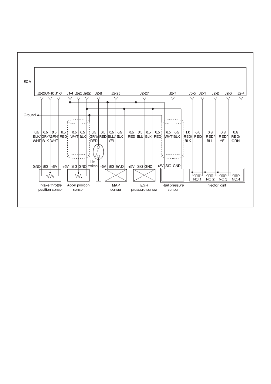
Diagnostic Trouble Code (DTC) P0107 (Flash DTC 34)
MAP Sensor Circuit Low Voltage
060RW134
Circuit Description
The manifold absolute pressure (MAP) sensor responds
to changes in intake manifold pressure (vacuum).
The ECM monitors the MAP signals for voltages outside
the normal range of the MAP sensor. If the ECM detects a
MAP signal voltage that is excessively low, DTC P0107
will be set.
Action Taken When the DTC Sets
D
The ECM will illuminate the malfunction indicator lamp
(MIL) the first time the fault is detected.
D
The ECM will store conditions which were present
when the DTC was set as Freeze Frame and in the
Failure Records data.
Conditions for Clearing the MIL/DTC
D
DTC P0107 can be cleared by using the Tech 2 “Clear
Info” function or by disconnecting the ECM battery
feed.
Diagnostic Aids
Check for the following conditions:
D
Turn on the ignition switch and stop the engine. At this
time, the boost pressure will be equal to the
atmospheric pressure and the signal voltage will
increase.
D
Check for intermittent codes.
D
The MAP sensor shares a ground with the ECT sensor,
and the Transmission Fluid Temperature sensor.
D
Poor connection at ECM – Inspect harness connectors
for backed-out terminals, improper mating, broken
locks, improperly formed or damaged terminals, and
poor terminal-to-wire connection.
D
Damaged harness – Inspect the wiring harness for
damage. If the harness appears to be OK, observe the
MAP display on the Tech 2 while moving connectors
and wiring harnesses related to the sensor. A change
in the display will indicate the location of the fault.
If DTC P0107 cannot be duplicated, the information
included in the Failure Records data can be useful in
determining vehicle mileage since the DTC was last set.
If it is determined that the DTC occurs intermittently,
performing the DTC P0107 Diagnostic Chart may isolate
the cause of the fault.

6E–57
4JX1–TC ENGINE DRIVEABILITY AND EMISSIONS
DTC P0107 – MAP Sensor Circuit Low Voltage
Step
Action
Value(s)
Yes
No
1
Was the “On-Board Diagnostic (OBD) System Check”
performed?
—
Go to
Step 2
Go to
OBD
System
Check
2
Put the engine into an idling status.
Is the MAP voltage value displayed on the Tech 2 below
the specified value?
0.25 V
Go to
Step 3
Refer to
Diagnostic
Aids and
Symptom
Diagnosis
3
1. Turn off the ignition switch.
2. Remove the sensor connector connection.
3. Jumper between harness pins “red” and “blue”
wires.
4. Turn on the ignition switch “ON”.
Is the MAP voltage reading above the specified value?
4 V
Go to
Step 5
Go to
Step 4
4
1. Turn off the ignition switch.
2. Remove the jumper wire.
3. Connect the relay & solenoid checker
(5-8840-0386-0) to the battery voltage, then check
the MAP signal circuit (blue wire).
4. Turn on the ignition switch.
Is the value displayed on the Tech 2 above the specified
value?
4 V
Go to
Step 6
Go to
Step 7
5
Check the terminal connection at the MAP sensor and
repair or replace terminal if necessary.
Is the action complete?
—
Verify repair
—
6
Repair the 5V power circuit (red) harness or Replace
the ECM (Refer to the Data Programming in Case of
ECM change).
Is the action complete?
—
Verify repair
—
7
Repair the signal circuit (blue) harness or Replace the
ECM (Refer to the Data Programming in Case of ECM
change).
Is the action complete?
—
Verify repair
—
Нет комментариевНе стесняйтесь поделиться с нами вашим ценным мнением.
Текст