Opel Frontera UBS. Service manual — part 2152

6E–181
ENGINE DRIVEABILITY AND EMISSIONS
DTC P0204 – Injector 4 Control Circuit
(Cont'd)
Step
No
Yes
Value(s)
Action
7
1. Disconnect the PCM connector for the affected
injectors.
2. With a test light connected to B+, probe the affected
injector driver circuit.
Does the test light illuminate?
—
Go to
Step 8
Go to
Step 15
8
Repair short to ground in the injector driver circuit.
Is the action complete?
—
Go to
OBD
System
Check
—
9
1. Disconnect the injector test connector.
2. At the injector side of the harness, connect an
ohmmeter between the positive wire (red with blue
tracer) and the wire for cylinder 4 (green/red).
Does the ohmmeter indicate continuity?
—
Go to
Step 11
Go to
Step 10
10
Repair the open injector harness wire or open injector.
Is the action complete?
—
Verify repair
—
11
At the PCM side of the injector test connector, check
the green/red wire for a short to voltage.
Was there a short to voltage?
—
Go to
Step 12
Go to
Step 13
12
Repair the short to voltage.
Is the action complete?
—
Verify repair
—
13
Check for an open circuit between the injector test
connector and the PCM.
Was there an open circuit?
—
Go to
Step 14
Go to
Step 15
14
Repair the open circuit.
Is the action complete?
—
Verify repair
—
15
Replace the PCM.
IMPORTANT: The replacement PCM must be
programmed. Refer to
UBS 98model year Immobilizer
Workshop Manual.
Is the action complete?
—
Verify repair
—
6E–182
ENGINE DRIVEABILITY AND EMISSIONS
Diagnostic Trouble Code (DTC) P0205 Injector 5 Control Circuit
D06RW034
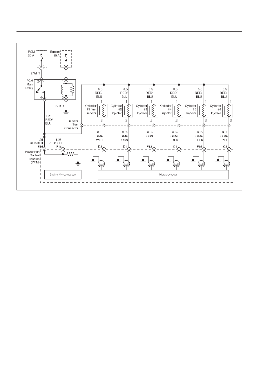
Circuit Description
The powertrain control module (PCM) has six individual
injector driver circuits. Each controls an injector. When
the driver circuit is grounded by the PCM, the injector is
activated. The PCM monitors the current in each driver
circuit. If the voltage is not what the PCM expects to
monitor on the circuit, a DTC is set. This DTC is also set if
an injector driver is shorted to voltage or if there is an open
circuit.
Conditions for Setting the DTC
D
The battery voltage is more than 9 volts.
D
The engine is turning, determined by the 58X
crankshaft position input signal.
D
The injector voltage does not equal the ignition voltage
when the injector is commanded “OFF” or the injector
voltage does not equal 0 volts when the injector is
commanded “ON.”
D
The above conditions are met for 15 seconds.
Action Taken When the DTC Sets
D
The PCM will illuminate the malfunction indicator lamp
(MIL) the first time the fault is detected.
D
The PCM will store conditions which were present
when the DTC was set as Freeze Frame and in the
Failure Records data.
Conditions for Clearing the MIL/DTC
D
DTC P0205 can be cleared by using the Tech 2 “Clear
Info” function or by disconnecting the PCM battery
feed.
Diagnostic Aids
An injector driver circuit that is open or shorted to voltage
will cause a DTC P0205 to set. It will also cause a misfire
due to an inoperative injector. A misfire DTC will also be
set indicating which cylinder is inoperative.
Long term and short term fuel trims that are excessively
high or low are a good indication that an injector is faulty.
Use Fuel Injector Coil Test Procedure to check for faulty
injectors.
Test Description
The number(s) below refer to the step number(s) on the
Diagnostic Chart.
3. This step determines if DTC P0205 is the result of a
hard failure or an intermittent condition.
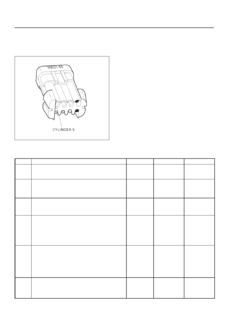
5. A special injector test connector is provided so that
the injectors can be electrically tested without
removal of the manifold. On the Trooper, the
special 7-way gray connector is located at the front
of the charcoal canister. The test connector can be
identified by the blue connector lock which is
tethered to the wiring harness. If the light for
cylinder 5 is “ON” steady before cranking the engine
as well as while cranking the engine, then the
injector driver circuit is shorted to ground.
6E–183
ENGINE DRIVEABILITY AND EMISSIONS
If the test light blinks while cranking, the PCM and
the wiring to the injectors are OK. The Fuel Injector
Coil Test Procedure will check if the injectors are
faulty.
R321058
7. Because the test light was “ON” steady, voltage to
the injector is OK, but the driver circuit is grounded
at all times. This step determines if the circuit is
shorted to ground or the PCM is faulty.
9. The reading should be about 12-14
W
.
10.Locating the open in the harness or in the injector
will require removal of the manifold to provide
access.
DTC P0205 – Injector 5 Control Circuit
Step
Action
Value(s)
Yes
No
1
Was the “On-Board Diagnostic (OBD) System Check”
performed?
—
Go to
Step 2
Go to
OBD
System
Check
2
Will the engine start?
—
Go to
Step 3
Go to
Engine
Cranks But
Will Not Run
chart
3
1. Install the Tech 2. Clear the DTC.
2. Idle the engine for one minute.
Does DTC P0205 reset?
—
Go to
Step 5
Go to
Step 4
4
1. Review the Freeze Frame data with the ignition
“ON” and the engine “OFF” and note the
parameters.
2. Operate the vehicle within the Freeze Frame
conditions as noted.
Does P0205 reset?
—
Go to
Step 5
Go to
Diagnostic
Aids
5
1. Engine “OFF.”
2. Disconnect the injector test connector.
3. Install an injector test light 5-8840-2636-0 on
injector connector.
4. Crank the engine and note the light.
Does the cylinder 5 test light blink?
—
Go to
Fuel
Injector Coil
Test
Procedure
Go to
Step 6
6
Note whether the injector test light for cylinder 5 was
“OFF” or “ON” steady in step 5.
Was the test light “ON” steady while cranking the
engine?
—
Go to
Step 7
Go to
Step 9

6E–184
ENGINE DRIVEABILITY AND EMISSIONS
DTC P0205 – Injector 5 Control Circuit
(Cont'd)
Step
No
Yes
Value(s)
Action
7
1. Disconnect the PCM connector for the affected
injectors.
2. With a test light connected to B+, probe the affected
injector driver circuit.
Does the test light illuminate?
—
Go to
Step 8
Go to
Step 15
8
Repair short to ground in the injector driver circuit.
Is the action complete?
—
Go to
OBD
System
Check
—
9
1. Disconnect the injector test connector.
2. At the injector side of the harness, connect an
ohmmeter between the positive wire (red with blue
tracer) and the wire for cylinder 5 (green with black
tracer).
Does the ohmmeter indicate continuity?
—
Go to
Step 11
Go to
Step 10
10
Repair the open injector harness wire or open injector.
Is the action complete?
—
Verify repair
—
11
At the PCM side of the injector test connector, check
the green/black wire for a short to voltage.
Was there a short to voltage?
—
Go to
Step 12
Go to
Step 13
12
Repair the short to voltage.
Is the action complete?
—
Verify repair
—
13
Check for an open circuit between the injector test
connector and the PCM.
Was there an open circuit?
—
Go to
Step 14
Go to
Step 15
14
Repair the open circuit.
Is the action complete?
—
Verify repair
—
15
Replace the PCM.
IMPORTANT: The replacement PCM must be
programmed. Refer to
UBS 98model year Immobilizer
Workshop Manual.
Is the action complete?
—
Verify repair
—
Нет комментариевНе стесняйтесь поделиться с нами вашим ценным мнением.
Текст