Opel Frontera UBS. Service manual — part 2697

8B–12 WIPER/WASHER SYSTEM
Headlight Wiper and Washer Switch
Removal
1. Disconnect the battery ground cable.
2. Remove the front console assembly(1).
Refer to the Instrument Panel Assembly in Body
Structure section.
3. Remove the lower cluster assembly(2).
Refer to the Instrument Panel Assembly in Body
Structure section.
4. Remove the instrument panel driver lower cover(3).
Refer to the Instrument Panel Assembly in Body
Structure section.
821RW024
5. Remove the instrument panel cluster assembly(4).
Refer to the Instrument Panel Assembly in Body
Structure section.
6. Disconnect the connector and push the lock from the
back side of the instrument panel cluster assembly to
remove the headlight wiper switch(5).
825RW245
Installation
To install, follow the removal steps in the reverse order,
noting the following point:
1. Push the switch with your fingers until it locks
securely.
WIPER/WASHER SYSTEM
8B–13
Headlight Wiper Arm & Blade
Removal
1. Remove the wiper arm nut and the wiper arm &
blade(1).
2. Disconnect the washer hose.
808RW001
Installation
To install, follow the removal steps in the reverse order,
noting the following point:
1. Tighten the wiper arm nut to the specified torque.
Torque: 5 N·m (0.5 kg·m/44 Ib ft)
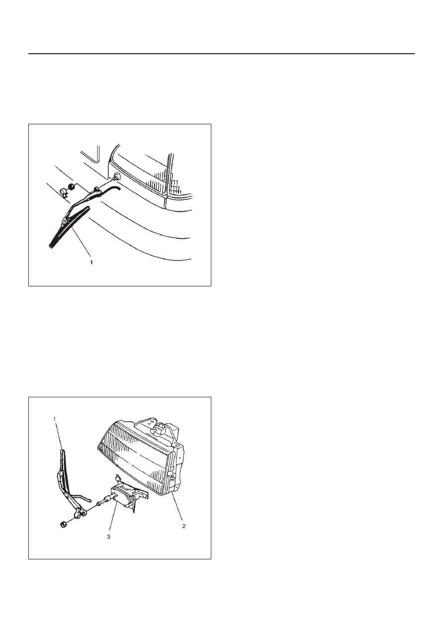
Headlight Wiper Motor
Removal
1. Disconnect the battery ground cable.
2. Remove the headlight wiper arm/blade(1).
3. Remove the headlight assembly(2).
Refer to the Headlight removal steps in this section.
4. Remove 2 nuts and screws, the remove headlight
wiper motor(3).
808RW002
Installation
To install, follow the removal steps in the reverse order,
noting the following point:
1. Make sure that the motor stops at auto stop position
prior to installing the wiper arm & blade to the motor
shaft.

8B–14 WIPER/WASHER SYSTEM
Headlight Washer Motor
Removal and Installation
Refer to the removal and installation steps of the
windshield washer tank/motor under »Windshield
Wiper/Washer And Rear Wiper/Washer” in this section.
Main Data and Specifications
Torque Specifications
Application
N·m
kg·m
Lb Ft
Lb In
Windshield Wiper Motor Shaft Nut
14
1.4
—
122
Windshield Wiper Arm Nuts
31
3.2
23
—
Rear Wiper Motor Shaft Nut
6
0.6
—
52
Rear Wiper Arm Nut
9
0.9
—
78
Headlight Wiper Arm Nuts
5
0.5
—
44
ENTERTAINMENT
8C–1
BODY AND ACCESSORIES
ENTERTAINMENT
CONTENTS
Service Precaution
8C–1
. . . . . . . . . . . . . . . . . . . . . .
Cigarette Lighter
8C–2
. . . . . . . . . . . . . . . . . . . . . . . .
General Description
8C–2
. . . . . . . . . . . . . . . . . . . . .
Removal
8C–2
. . . . . . . . . . . . . . . . . . . . . . . . . . . . .
Installation
8C–2
. . . . . . . . . . . . . . . . . . . . . . . . . . . .
Digital Clock
8C–3
. . . . . . . . . . . . . . . . . . . . . . . . . . . .
Removal
8C–3
. . . . . . . . . . . . . . . . . . . . . . . . . . . . .
Installation
8C–3
. . . . . . . . . . . . . . . . . . . . . . . . . . . .
Rod Type Antenna
8C–4
. . . . . . . . . . . . . . . . . . . . . .
Removal
8C–4
. . . . . . . . . . . . . . . . . . . . . . . . . . . . .
Installation
8C–4
. . . . . . . . . . . . . . . . . . . . . . . . . . . .
Auto Antenna
8C–5
. . . . . . . . . . . . . . . . . . . . . . . . . . .
General Description
8C–5
. . . . . . . . . . . . . . . . . . . . .
Removal
8C–5
. . . . . . . . . . . . . . . . . . . . . . . . . . . . .
Installation
8C–5
. . . . . . . . . . . . . . . . . . . . . . . . . . . .
Antenna Rod
8C–6
. . . . . . . . . . . . . . . . . . . . . . . . . . .
Removal
8C–6
. . . . . . . . . . . . . . . . . . . . . . . . . . . . .
Installation
8C–6
. . . . . . . . . . . . . . . . . . . . . . . . . . . .
Radio
8C–7
. . . . . . . . . . . . . . . . . . . . . . . . . . . . . . . . . .
Removal
8C–7
. . . . . . . . . . . . . . . . . . . . . . . . . . . . .
Installation
8C–7
. . . . . . . . . . . . . . . . . . . . . . . . . . . .
Front Speaker
8C–8
. . . . . . . . . . . . . . . . . . . . . . . . . .
Removal
8C–8
. . . . . . . . . . . . . . . . . . . . . . . . . . . . .
Installation
8C–8
. . . . . . . . . . . . . . . . . . . . . . . . . . . .
Rear Speaker
8C–9
. . . . . . . . . . . . . . . . . . . . . . . . . . .
Removal
8C–9
. . . . . . . . . . . . . . . . . . . . . . . . . . . . .
Installation
8C–9
. . . . . . . . . . . . . . . . . . . . . . . . . . . .
Service Precaution
WARNING: IF SO EQUIPPED WITH A
SUPPLEMENTAL RESTRAINT SYSTEM (SRS),
REFER TO THE SRS COMPONENT AND WIRING
LOCATION VIEW IN ORDER TO DETERMINE
WHETHER YOU ARE PERFORMING SERVICE ON OR
NEAR THE SRS COMPONENTS OR THE SRS
WIRING. WHEN YOU ARE PERFORMING SERVICE
ON OR NEAR THE SRS COMPONENTS OR THE SRS
WIRING, REFER TO THE SRS SERVICE
INFORMATION. FAILURE TO FOLLOW WARNINGS
COULD RESULT IN POSSIBLE AIR BAG
DEPLOYMENT, PERSONAL INJURY, OR
OTHERWISE UNNEEDED SRS SYSTEM REPAIRS.
CAUTION: Always use the correct fastener in the
proper location. When you replace a fastener, use
ONLY the exact part number for that application.
ISUZU will call out those fasteners that require a
replacement after removal. ISUZU will also call out
the fasteners that require thread lockers or thread
sealant. UNLESS OTHERWISE SPECIFIED, do not
use supplemental coatings (Paints, greases, or other
corrosion inhibitors) on threaded fasteners or
fastener joint interfaces. Generally, such coatings
adversely affect the fastener torque and the joint
clamping force, and may damage the fastener. When
you install fasteners, use the correct tightening
sequence and specifications. Following these
instructions can help you avoid damage to parts and
systems.
Нет комментариевНе стесняйтесь поделиться с нами вашим ценным мнением.
Текст