Opel Frontera UBS. Service manual — part 1733
8F–3
BODY STRUCTURE
Parts Location
8F–102
. . . . . . . . . . . . . . . . . . . . . . . .
Removal
8F–102
. . . . . . . . . . . . . . . . . . . . . . . . . . . . .
Installation
8F–103
. . . . . . . . . . . . . . . . . . . . . . . . . . . .
Main Data and Specifications
8F–104
. . . . . . . . . . . . .
Special Tools
8F–115
. . . . . . . . . . . . . . . . . . . . . . . . . . .
Service Precaution
WARNING: THIS VEHICLE HAS A SUPPLEMENTAL
RESTRAINT SYSTEM (SRS). REFER TO THE SRS
COMPONENT AND WIRING LOCATION VIEW IN
ORDER TO DETERMINE WHETHER YOU ARE
PERFORMING SERVICE ON OR NEAR THE SRS
COMPONENTS OR THE SRS WIRING. WHEN YOU
ARE PERFORMING SERVICE ON OR NEAR THE SRS
COMPONENTS OR THE SRS WIRING, REFER TO
THE SRS SERVICE INFORMATION. FAILURE TO
FOLLOW WARNINGS COULD RESULT IN POSSIBLE
AIR BAG DEPLOYMENT, PERSONAL INJURY, OR
OTHERWISE UNNEEDED SRS SYSTEM REPAIRS.
CAUTION: Always use the correct fastener in the
proper location. When you replace a fastener, use
ONLY the exact part number for that application.
ISUZU will call out those fasteners that require a
replacement after removal. ISUZU will also call out
the fasteners that require thread lockers or thread
sealant. UNLESS OTHERWISE SPECIFIED, do not
use supplemental coatings (Paints, greases, or other
corrosion inhibitors) on threaded fasteners or
fastener joint interfaces. Generally, such coatings
adversely affect the fastener torque and the joint
clamping force, and may damage the fastener. When
you install fasteners, use the correct tightening
sequence and specifications. Following these
instructions can help you avoid damage to parts and
systems.
Frame
General Description
Proper frame alignment is important to assure normal
vehicle life and performance of many other parts of the
vehicle. If the vehicle has been involved in a fire, collision
or has been overloaded, it is necessary to check the
frame alignment.
8F–4
BODY STRUCTURE
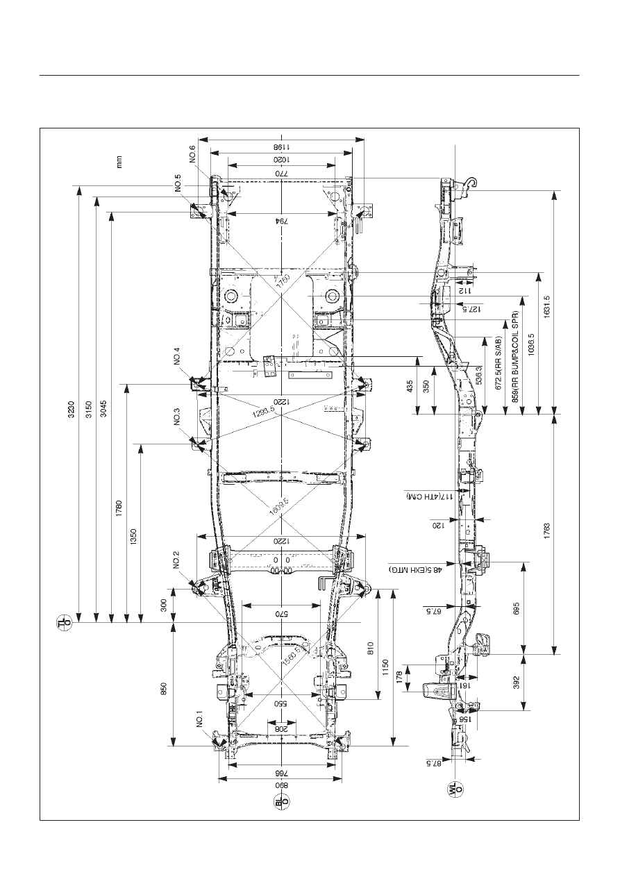
Frame Dimensions (L W B)
This illustration is based on the gasoline engine and A/T
model.
501RW013
8F–5
BODY STRUCTURE
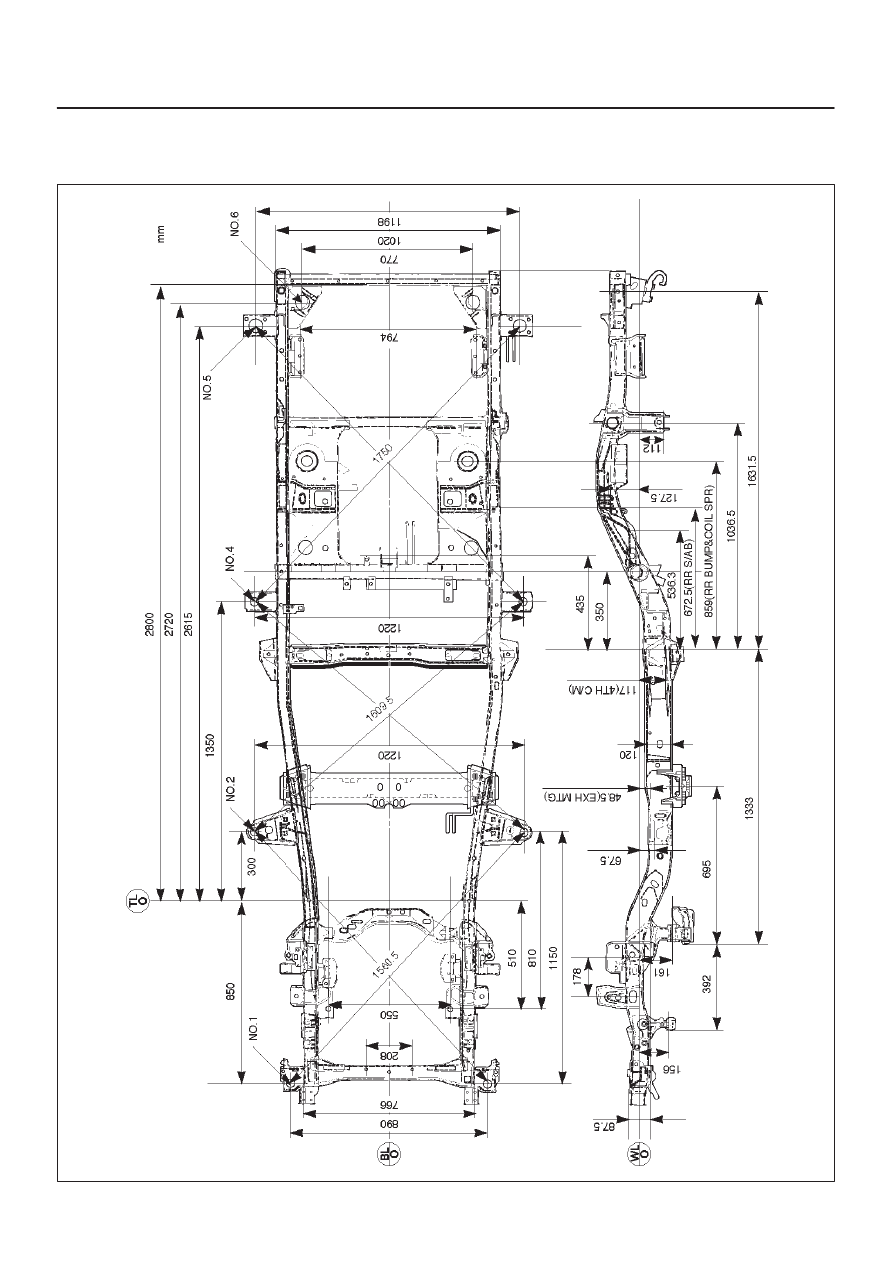
Frame Dimensions (S W B)
This illustration is based on the gasoline engine and A/T
model.
501RW014
8F–6
BODY STRUCTURE
General Description
This section describes how to remove and install front
and rear bumpers. Each bumper is installed with two
fixing bolts used on either side to fasten the backbar to the
frame, a slider is used to fasten the bumper fascia to the
fender panel. The bumpers can be removed by taking
them out forward or backward after removing the two
fixing bolts on either side.
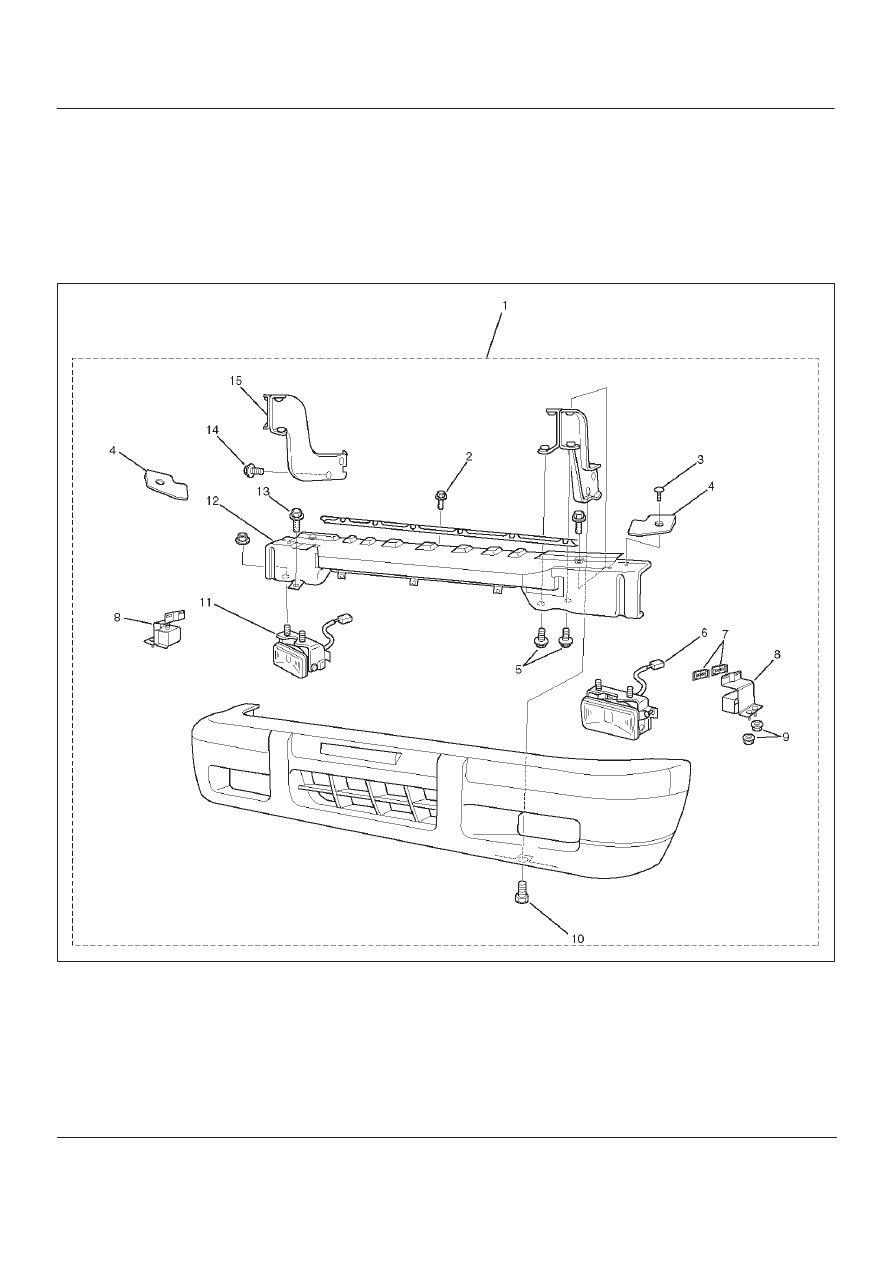
Front Bumper
Parts Location
601RX001
Legend
(1) Front Bumper Assembly
(2) Front Bumper Retainer Bolt
(3) Support Fixing Clip
(4) Bumper Spacer Support
(5) Back Bar Fixing Bolt
(6) Front Fog Light Connector
(7) Front Bumper Slider Fixing Clip
(8) Front Bumper Slider
(9) Front Bumper Slider Fixing Nut
(10) Bumper Fascia Lower Bolt
(11) Front Fog Light Assembly
(12) Reinforce Assembly
(13) Reinforce Lower Bolt
(14) Front Bumper Fixing Bolt
(15) Back Bar
Нет комментариевНе стесняйтесь поделиться с нами вашим ценным мнением.
Текст