Opel Frontera UBS. Service manual — part 1042

DRIVE LINE CONTROL SYSTEM (TOD)
4B2–108
Step
Action
Yes
No
1
Start the engine.
When the transfer lever is shifted to the neutral position between
high and 4L, is 5V observed between terminals 10 and 19?
Go to Step 2
Go to Step 7
2
When the transfer lever is shifted to the high position and 4WD
AUTO SW is selected to the 4WD position, is 0V observed
between terminals 10 and 19?
Go to Step 3
Go to Step 7
3
When the transfer lever is shifted to the 4L position, is 0V
observed between terminals 10 and 19?
Go to Step 4
Go to Step 7
4
Select the 4WD AUTO SW to the 2WD position.
Is 12V observed between terminals 25 and 19?
Go to Step 5
Replace the
ECU.
Go to Step 19
5
Is 12V observed between terminals 26 and 19?
Go to Step 6
Replace the
ECU.
Go to Step 19
6
Is 12V observed between terminals 27 and 19?
The phenomenon
is not
reproduced.
Refer to
“Troubles
intermittently
observed”.
The ECU has
failed. Replace
the ECU.
Go to Step 19
7
When the 4WD AUTO SW is selected to the 2WD position, is the
battery voltage observed between terminals 5 and 19?
Go to Step 8
Go to Step 11
8
When the transfer lever is shifted to the neutral position between
high and 4L, is the battery voltage observed between terminals 5
and 19?
Go to Step 9
Go to Step 11
9
When the transfer lever is shifted to the high position and 4WD
AUTO SW is selected to the 4WD position, is 0V observed
between terminals (B–67)5 and (B–67)11?
Go to Step 10
Go to Step 11
10
When the transfer lever is shifted to the 4L position, is 0V
observed between terminals 5 and 19?
Go to Step 12
Go to Step 11
11
Is any of the trouble codes 28, 32 and 33 recorded?
Examine the
trouble based on
“Diagnosis from
Trouble Codes”.
The ECU has
failed. Replace
the ECU.
12
1. Turn off the starter switch.
2. Disconnect the ECU connector.
Does the resistance between terminals 5 and 19 meet the
standard, 17< R < 25 ohm?
Go to Step 13
Repair the circuit
or replace the
VSV.
Go to Step 19
13
1. Connect the ECU connector.
2. Turn on the starter switch.
When the 4WD AUTO SW is selected to the 2WD position, is the
battery voltage supplied to each VSV?
Go to Step 14
Repair the circuit
or replace the
VSV.
Go to Step 19
14
When the transfer lever is shifted to the neutral position between
high and 4L, is the battery voltage supplied to each VSV?
Go to Step 15
Repair the circuit
or replace the
VSV.
Go to Step 19
15
When the transfer lever is shifted to the high position and 4WD
AUTO SW is selected to the 4WD position, is 0V observed on
each VSV?
Go to Step 16
Repair the circuit
or replace the
VSV.
Go to Step 19
4B2–109
DRIVE LINE CONTROL SYSTEM (TOD)
Step
No
Yes
Action
16
When the transfer lever is shifted to the 4L position, is 0V
observed on each VSV?
Go to Step 17
Repair the circuit
or replace the
VSV.
Go to Step 19
17
Is the vacuum pressure supplied to the VSV?
Go to Step 18
Repair the
vacuum system.
Go to Step 19
18
Can the single AXLE switch enable and disable the continuity?
Repair the shift
on the fly system
Refer to Section
4B1 and 4C.
Go to Step 19
Replace the
AXLE switch
Refer to Section
4B1 and 4C.
Go to Step 19
19
Check that all the parts are mounted.
Is this step complete?
Repeat the
“Diagnosis Flow”.
Return to Step 19
DRIVE LINE CONTROL SYSTEM (TOD)
4B2–110
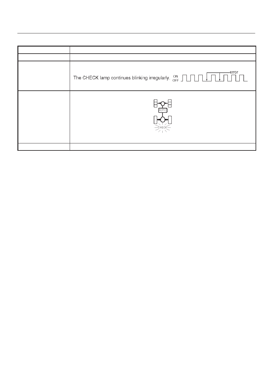
Chart G
The trouble codes are displayed.
Function of circuit
—
Fail condition
Indicator lamp status
Transfer position
—
4B2–111
DRIVE LINE CONTROL SYSTEM (TOD)
D04RY00072
Step
Action
Yes
No
1
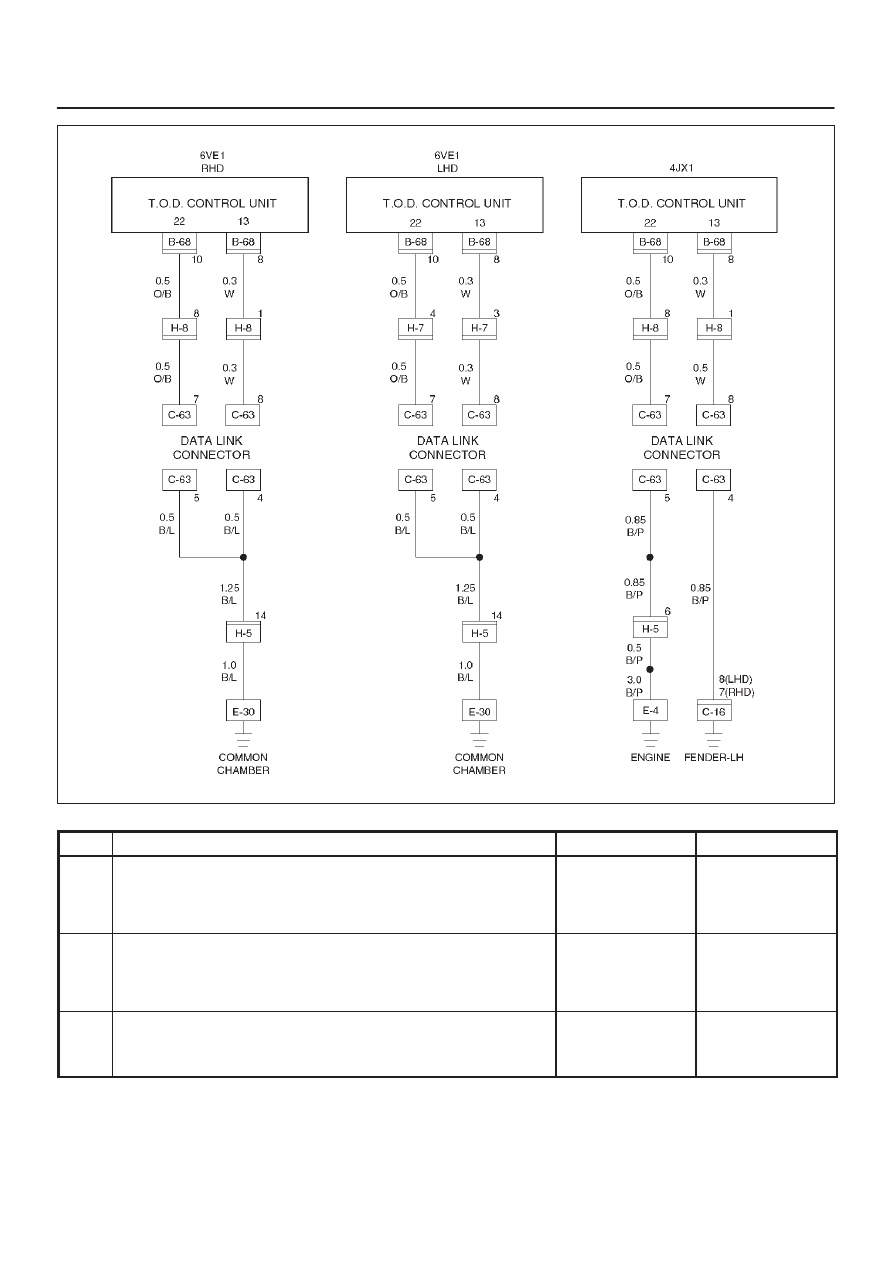
Disconnect the ECU connector from ECU.
Is the continuity established between terminals (B–68)8 and
(B–67)11?
Go to Step 2
The ECU has
failed. Replace
the ECU.
Go to Step 3
2
Is the self-diagnostic connector short-circuited?
Go to Step 3
Repair the
self-diagnostic
connector circuit.
Go to Step 3
3
1. Check that all the parts are mounted.
2. Clear the trouble codes.
Is this step complete?
Repeat the
“Diagnosis Flow”.
Return to Step 3
Нет комментариевНе стесняйтесь поделиться с нами вашим ценным мнением.
Текст