Opel Frontera UBS. Service manual — part 1333
6A – 82 ENGINE MECHANICAL
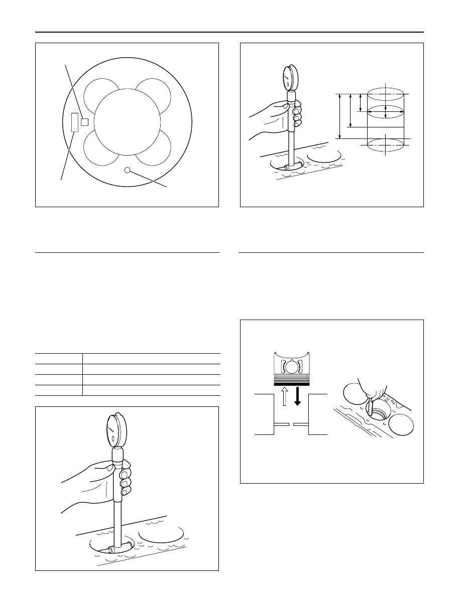
Legend
(1) Piston Grade
(2) Piston Front Mark
(3) Part Number
The grade for piston outside diameter is stamped
on the piston head.
Measure the cylinder bore diameter at measuring
points.
If the piston clearance does not conform to the
specified value, the pistons most be replaced.
Piston Clearance:
0.092 – 0.110 mm (0.0036 – 0.0043 in)
Cylinder Bore Diameter
mm(in)
Grade Mark
Cylinder Bore Diameter
A
95.421 – 95.430 (3.7567 – 3.7571)
B
95.431 – 95.440 (3.7571 – 3.7575)
C
95.441 – 95.450 (3.7575 – 3.7579)
Legend
Measuring point 1 = 20 mm
2 = 90 mm
3 = 160 mm
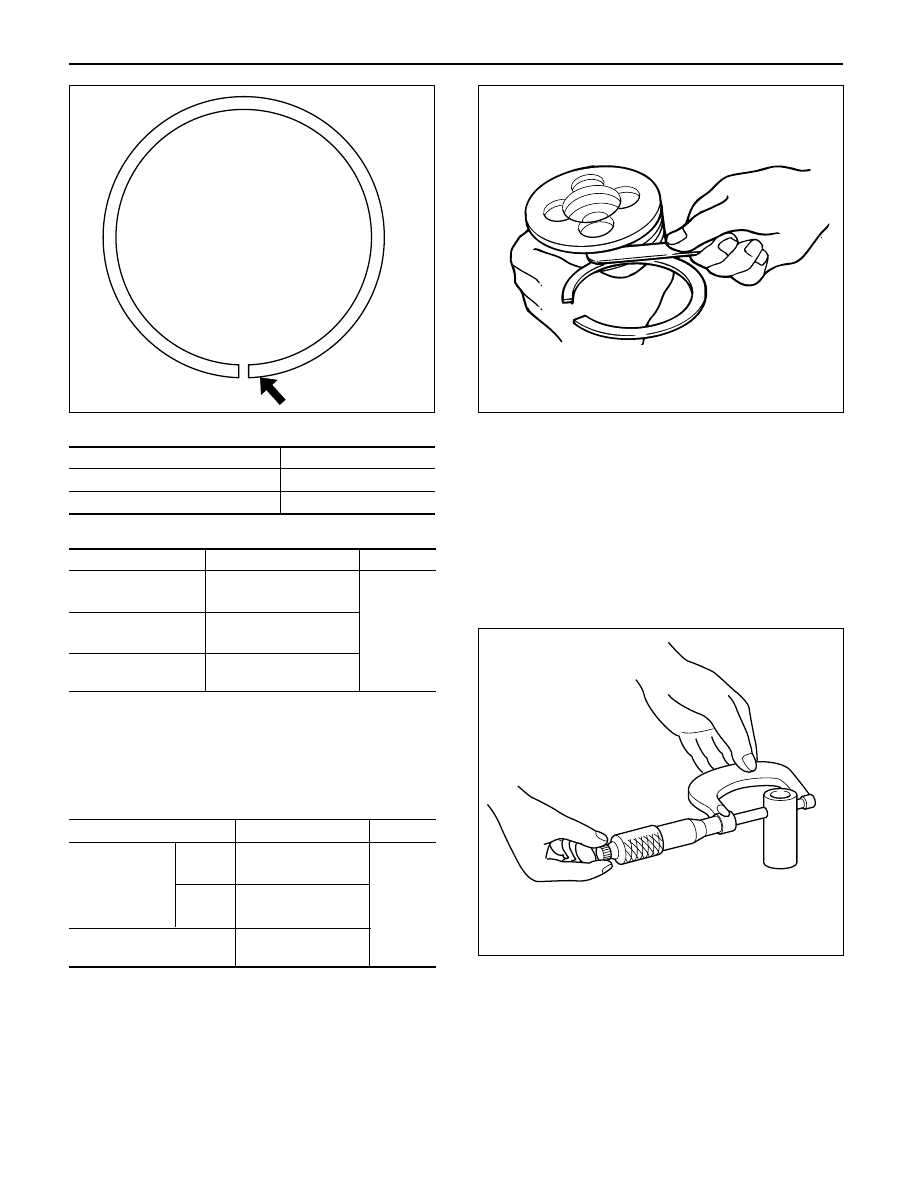
Piston rings
Any worn or damaged part discovered during engine
overhaul must be replaced with a new one.
1. Ring end gap measurement
1) Insert the piston ring into the cylinder bore.
2) Push the ring by the piston, at the right angle to
the wall, into the point at which the cylinder bore
diameter is the smallest.
3) Measure the ring end gap.
NOTE: The piston ring is stamped with a discerning
mark on the upper face of piston ring.
1
3
2
015RW080
012RW071
3
2
1
012RW117
012RW051
ENGINE MECHANICAL 6A – 83
Discerning Mark
Piston Ring
Discerning Mark
1st compression ring
1N
2nd compression ring
2N
Ring End Gap
mm(in)
Piston Ring
Standard Gap
Limit
1st
0.25 – 0.40
compression ring
(0.0098 – 0.0157)
2nd
0.20 – 0.35
1.5
compression ring
(0.0079 – 0.0138)
(0.0590)
Oil ring
0.10 – 0.30
(0.0039 – 0.0118)
2. Measure the clearance between the piston ring
groove and the piston ring with a feeler gauge. If the
piston ring groove/piston ring clearance exceeds
the specified limit, the piston and/or piston rings
must be replaced.
mm(in)
Standard
Limit
1st
0.05 – 0.09
Compression
(0.0020 – 0.0035)
ring
2nd
0.05 – 0.09
0.15
(0.0020 – 0.0035)
(0.0059)
Oil ring
0.03 – 0.07
(0.0012 – 0.0028)
Piston pin
Visually inspect the piston pin for cracks, flaws, and
other damage and replace if necessary.
1. Use a micrometer to measure the piston pin outside
diameter in both directions at three different
positions. If the measurement exceeds the
specified limit, the piston pin must be replaced.
Standard: 30.995 – 31.000 mm (1.2212 – 1.2214 in)
Limit: 30.97 mm (1.2202 in)
N
012RW037
015RW076
012RW082
6A – 84 ENGINE MECHANICAL
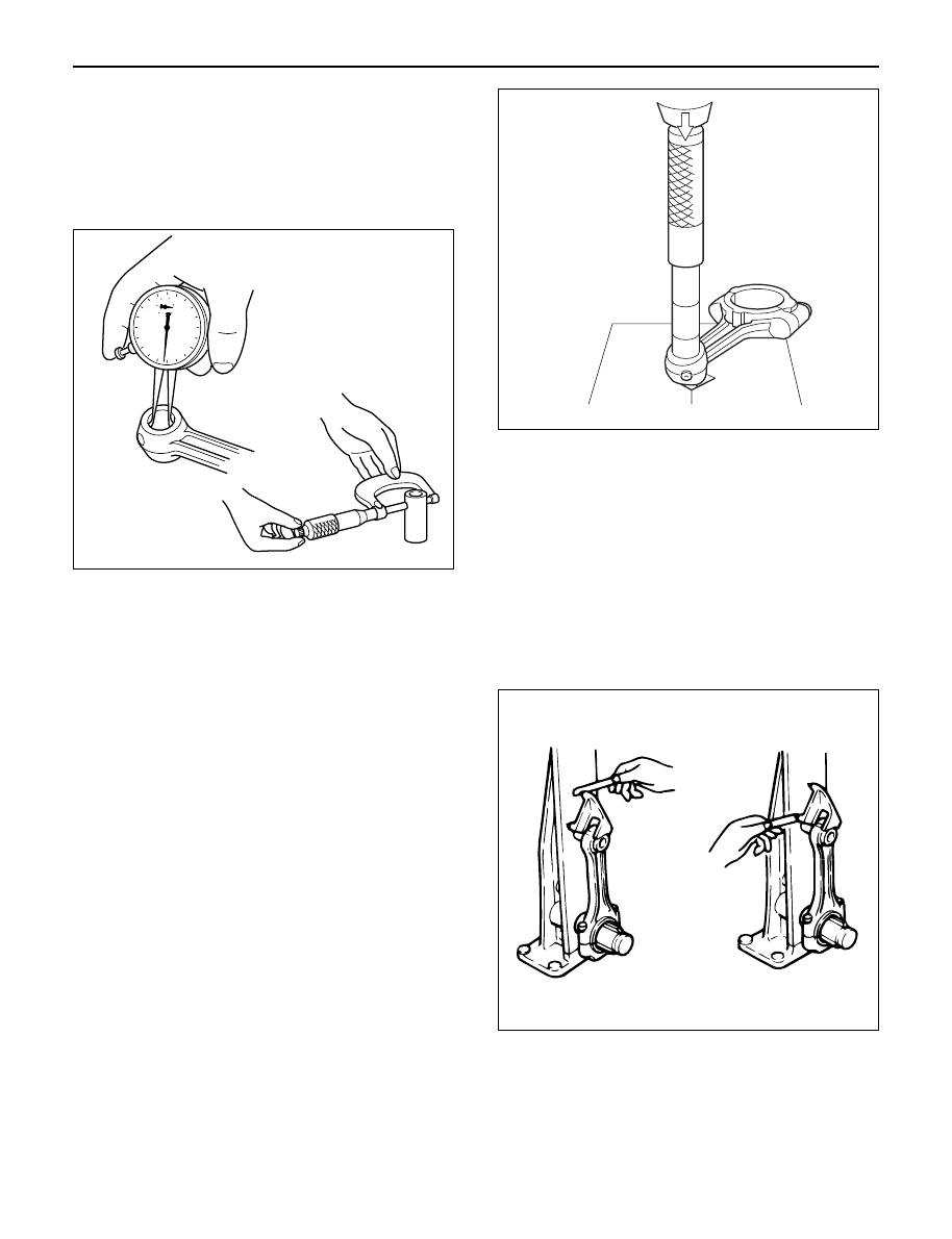
2. Measure the inside diameter of the connecting rod
small end. If the clearance between the small end
and pin does not conform to the specified value, the
connecting rod or bushing and pin must be
replaced.
Standard: 0.008 – 0.020 mm (0.0003 – 0.0008 in )
Limit: 0.05 mm (0.0020 in)
3. Insert the piston pin into the piston and rotate it. If
the pin rotates smoothly with no backlash, the
clearance is normal. If there is backlash or
roughness, measure the clearance. If the clearance
exceeds the specified limit, the piston and the
piston pin must be replaced.
Standard: 0.005 – 0.018 mm (0.0002 – 0.0007 in )
Limit: 0.04 mm (0.0016 in)
Bushing replacement
Removal:
Use a suitable bar and bench press or
hammer
Installation:
Align the bushing with a connecting rod
oil port. After installing a new bushing,
finish the bushing bore with a pin hole
grinder.
Connecting rods
1. Check the connecting rod alignment with a
connecting rod aligner.
If either the bend or the twist exceeds the specified
limit, the connecting rod must be replaced.
Bend per 100 mm (3.937 in)
Standard: 0.08 mm (0.0031 in) or less
Limit: 0.20 mm (0.0079 in)
Twist per 100 mm (3.937 in)
Standard: 0.05 mm (0.0020 in) or less
Limit: 0.15 mm (0.0059 in)
2. Measure the connecting rod thrust clearance.
Use a feeler gauge to measure the thrust clearance
at the big end of the connecting rod.
If the clearance exceeds the specified limit, the
connecting rod must be replaced.
Standard: 0.230 mm (0.0091 in)
Limit: 0.350 mm (0.0138 in)
012RW074
012RW123
012RW001
ENGINE MECHANICAL 6A – 85
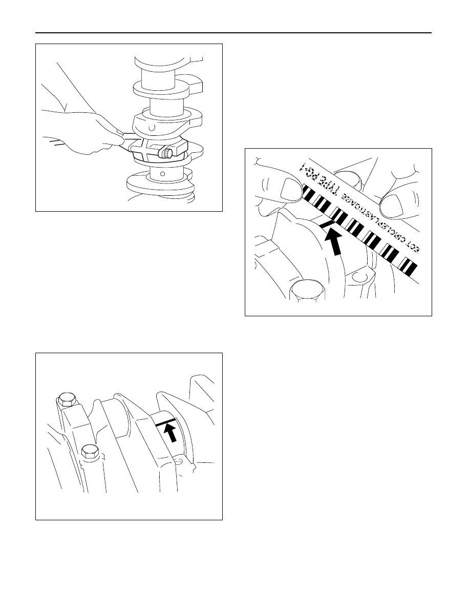
3. Measure the oil clearance between the connecting
rod and the crankshaft.
1) Remove the connecting rod cap nuts and the
rod caps.
Arrange the removed rod caps in the cylinder
number order.
2) Clean the rod bearings and the crankshaft pins.
3) Carefully check the rod bearings.
If even one bearing is found to be damaged or
badly worn, the entire bearing assembly must be
replaced as a set. Reinstall the bearings in their
original positions.
Apply plastigage to the crank pin.
4) Reinstall the rod caps to their original positions.
5) Tighten the cap nuts in 2 steps, using angular
tightening method as shown in the following
specifications.
1st step: 29 N·m (3.0 kg·m/22 lb ft)
2nd step: 45°– 60°
NOTE: Do not allow the crankshaft to rotate
6) Remove the rod caps.
7) Measure the smallest width of the plastigage
and determine the oil clearance. If the oil
clearance exceeds the limit, replace the rod
bearings as a set.
8) Clean the plastigage from the bearings and the
crankshaft pins
Standard: 0.022 – 0.042 mm (0.0009 – 0.0017 in)
Limit: 0.100 mm (0.0039 in)
REASSEMBLY
1. Connecting Rod
2. Piston
3. Piston Pin
1) Apply a coat of engine oil to the piston pin and
the piston pin hole.
4. Piston Pin Snap Ring
1) Try to insert the piston pin into the piston pin
hole with normal finger pressure.
2) Weight each piston and connecting rod
assembly.
3) Select piston and connecting rod combinations
so that the weight variation of the different four
assemblies is held within the specified limits.
Variance in weight after assembly: Less than 3g
(0.1058 oz)
NOTE: When changing piston/connecting rod
combinations, do not change the piston/piston pin
combination.
4) Attach the piston to the connecting rod with the
piston front mark (2) and the connecting rod
front mark (3) on the same side.
014RW055
012RW075
014RW077
Нет комментариевНе стесняйтесь поделиться с нами вашим ценным мнением.
Текст